Service, replacement parts and maintenance, Notice, Caution – Watts Governor 80M2 User Manual
Page 3: Warning
3
* The wetted surface of this product contacted by consumable water contains less than 0.25% of lead by weight.
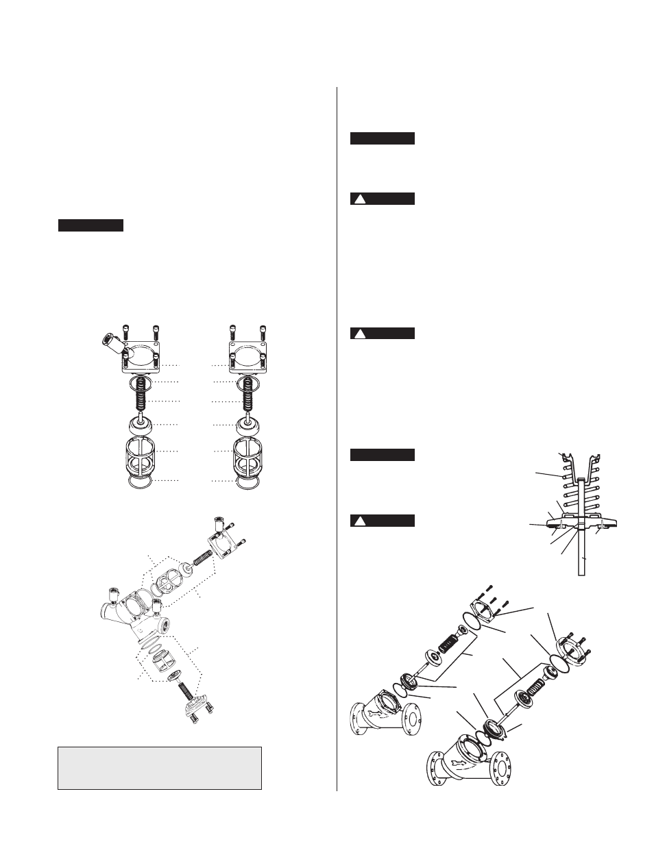
First Check
Second Check
Cover
Cover
O-ring
Spring
Disc
Holder
Assembly
Seat
Seat
O-ring
Rubber
Parts Kit
F i r s t
C h e c k
Kit
Second
Check Kit
Rubber
Parts Kit
Spring Retainer
(Do Not Remove)
Spring
O-ring
Spring Retainer
(Do Not Remove)
Disc
Disc Holder
Retaining
Ring
Disc Retainer
Allen Head
Socket
Screws
Stem
Disc Holder
2
1
⁄
2
", 3" (65-80mm)
4" - 10" (100-250mm)
Cover
Cover
O-ring
**Disc &
Spring
Assembly
Seat
Seat
O-ring
Retainer
Wire
Service, Replacement Parts and Maintenance
Series 709/LF709/709DCDA
For repair kits and parts, refer to Backflow
Prevention Products Repair Kits & Service Parts
price list PL-RP-BPD on
www.watts.com
2
1
⁄
2
" – 10" (65-250mm) and
3" – 10" (80-250mm)
1. Remove hatch cover bolts.
NOTICE
The 709 and LF709 is designed so that, when the bolts are
backed off
1
⁄
2
", all the spring load is released from the cover
and retained by the check module.
CAUTION
!
Be sure to verify this before removing all the bolts.
2. Lift check valve module straight out, taking care not to hit
and damage seat ring.
3. The seat ring may be removed and replaced by pulling out
the two wire retainers. The wire retainers are 10" long. One
is drawn out clockwise and the other is drawn out counter-
clockwise.
4. With the retainer wires removed, the seat ring can be lifted
straight up and removed.
CAUTION
!
The check valve disc and spring assembly are in compression. The
spring load is captured by the two spring retainers and the stem.
The spring retainers are not to be removed for servicing. If there is
a need to replace the spring, spring retainer or stem, replace the
disc and spring assembly. If the disc holder has been damaged by
freezing or severe water hammer, it can be replaced in the field.
Remove the disc holder retaining ring and slide the disc holder off
the stem. Remove the o-ring from the stem and replace with a new
one. Apply grease to the o-ring and slide the new disc holder into
place. Re-install the retaining ring.
NOTICE
The disc holder should not be removed
when servicing only the disc, remove
allen head screws holding the disc
retaining plate and replace disc.
WARNING
!
** Spring assembly is factory assembled.
DO NOT DISASSEMBLE.
3
⁄
4
" – 2" (20-50mm)
1. After removing the cover screws, the check comes out with
the cover.
2. Holding the check Valve module in both hands, rotate the
assembly
1
⁄
4
turn. This will disengage the disc and spring
assembly into individual components. The disc assembly
may be cleaned or replaced. O-rings should be cleaned or
replaced as necessary and lightly greased with the FDA
approved silicon grease. Reassemble the check valve mod-
ule in the reverse order.
NOTICE
The springs of the first and second check valves are inter-
changeable.
(Before servicing, be certain water is turned off or shutoff valves
are closed)