Installation instructions, Outdoor installations, Indoor installations – Watts Governor 80M2 User Manual
Page 2
2
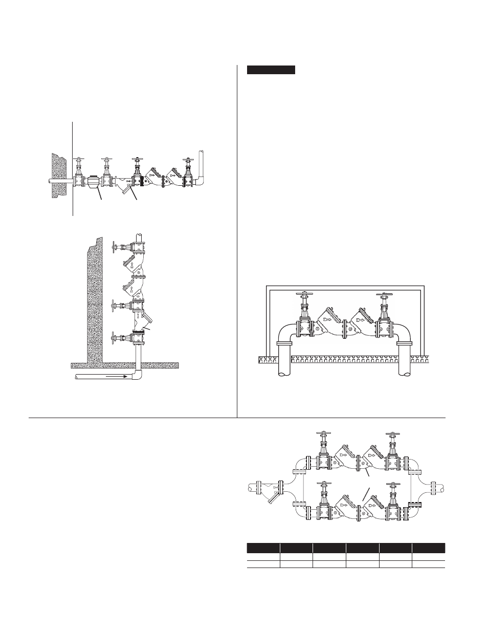
Vertical
Horizontal
Watts 709S/
LF709S
2
1
⁄
2
" – 10"
Strainer
For indoor installations, it is important that the valve be easily
accessible to facilitate testing and servicing.
Meter
Strainer
Watts 709S/LF709S
2
1
⁄
2
" – 10" (65-250mm)
Installation Instructions
Series 709/LF709/709DCDA
Parallel Installations
Two or more Series 709 and LF709 devices may be piped in paral-
lel (where approved) to serve a large supply pipe main. This type of
installation is employed whenever it is vital to maintain a continuous
supply of water where interruptions for testing and servicing would
be unacceptable. It also has the advantage of providing increased
capacity where needed beyond that provided by a single valve.
For two valve installations the total capacity of the devices should
equal or exceed that required by the system. Capacity table shows
the size of the Series 709 and LF709 devices required to meet a
certain capacity. The quantity of devices used in parallel should be
determined by the engineers judgement based on the operating
conditions of a specific installation.
Above Ground Insulated Enclosure
WattsBox Insulated
Enclosure Available in
Aluminum or Fiberglass
For more information, reference ES-WB at
www.watts.com
NOTICE
Outdoor Installations
In area where freezing conditions do not occur, Series 709 and
LF709 can be installed outside of a building. The most satisfactory
installation is above ground and should be installed in this manner
whenever possible.
It is generally recommended that backflow preventers never be
placed in pits unless absolutely necessary and then only when
approved by local codes. In such cases, a modified pit installation
is preferred or an above ground insulated enclosure.
Watts 709/LF709
2
1
⁄
2
" - 10"
Indoor Installations
For indoor installations, it is important that the valve be easily
accessible to facilitate testing and servicing.
Capacity Required for System
450 GPm
640 GPm
1000 GPm
2000 GPm
3000 GPm
5000 GPm
Two 2
1
⁄
2
"
Two 3"
Two 4"
Two 6"
Two 8"
Two 10"
Devices
Devices
Devices
Devices
Devices
Devices
Table shows total capacity provided with dual valve installations of
various sizes.