Ii. controls, indicators, and components, C. pretreatment, A. general system component identification – Watts PWR4021 User Manual
Page 3
3
C. Pretreatment
The RO feed water must be pretreated in order to prevent mem-
brane damage and/or fouling. Proper pretreatment is essential for
reliable operation of any RO system.
Pretreatment requirements vary depending on the nature of the feed
water. Pretreatment equipment is sold separately. The most common
forms of pretreatment are described below.
Media Filter - Used to remove large suspended solids (sediment)
from the feed water. Backwashing the media removes the trapped
particles. Backwash can be initiated by time or differential pressure.
Water Softener - Used to remove calcium and magnesium from
the feed water in order to prevent hardness scaling. The potential
for hardness scaling is predicted by the Langelier Saturation Index
(LSI). The LSI should be zero or negative throughout the unit unless
approved anti-scalents are used. Softening is the preferred method
of controlling hardness scale.
Carbon Filter - Used to remove chlorine and organics from the
feed water. Free chlorine will cause rapid irreversible damage to the
membranes.
The residual free chlorine present in most municipal water supplies
will damage the thin film composite structure of the membranes
used in this unit. Carbon filtration or sodium bisulfite injection should
be used to completely remove the free chlorine residual.
Chemical Injection - Typically used to feed antiscalant, coagulant,
or bisulfite into the feed water or to adjust the feed water pH.
Prefilter Cartridge - Used to remove smaller suspended solids and
trap any particles that may be generated by the other pretreatment.
The cartridge(s) should be replaced when the pressure drop across
the housing increases 5 - 10 psig over the clean cartridge pressure
drop. The effect of suspended solids is measured by the silt density
index (SDI) test. An SDI of five (5) or less is specified by most mem-
brane manufacturers and three (3) or less is recommended.
Iron & Manganese - Iron should be removed to less than 0.1 ppm.
Manganese should be removed to less than 0.05 ppm. Special me-
dia filters and/or chemical treatment is commonly used.
pH - The pH is often lowered to reduce the scaling potential.
Silica: Reported on the analysis as SiO2. Silica forms a coating on
membrane surfaces when the concentration exceeds its solubility.
Additionally, the solubility is highly pH and temperature dependent.
Silica fouling can be prevented with chemical injection and/or reduc-
ing the recovery.
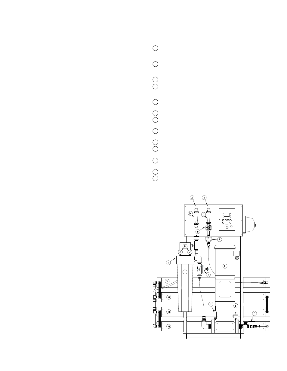
II. Controls, Indicators, and
Components
(See Figure 1)
A. General System Component Identification
A Controller - Controls the operation of the system and displays
the product water quality. This system uses the micro-electronic
based CI-1000 controller.
B Reject Control Valve - Controls the amount of reject flow. A
separate reject recycle water control valve is included to regulate
waste water recovery.
C Pump Discharge Valve - Used to throttle the pump.
D Prefilter Pressure Gauges - Indicates the inlet and outlet pres-
sure of the prefilter. The difference between these two gauges is
the prefilter differential pressure.
E Pump Discharge Pressure Gauge - Indicates the pump dis-
charge pressure.
F Reject Pressure Gauge - Indicates the reject pressure.
G Reject Flow Meter - Indicates the reject flow rate in gallons per
minute (gpm). A reject recycle flow meter is also included.
H Product Flow Meter - Indicates the product flow rate in gallons
per minute (gpm).
I Prefilter Housing - Contains the RO prefilter.
J Automatic Inlet Valve - Opens when pump is on and closes
when the pump is off.
K Low-pressure Switch - Sends a signal to the controller if the
pump suction pressure is low.
L RO Feed Pump - Pressurizes the RO feed water.
M RO Membrane Vessels - Contains the RO membranes.
Figure 1
Separate motor starter
enclosure used only with
CI 1000 controller.
Figure 1