Drinking water module mounting, Start up instructions, Adapt-a-valve™ installation – Watts PWDWLCV2 User Manual
Page 5: Configuration for, Configuration, Step 3, Step 4
5
STEP 3
Drinking Water Module Mounting
Step A – Determine best location for
the Drinking Water system to
be mounted to allow for future
system maintenance . The
parts bag has 2 self tapping
screws . Using an electric drill
with a Phillips bit, screw them
into the cabinet wall 6" apart
and 16" from the bottom of the
cabinet .
Note: Do not cut any Drinking Water system tubes at this time
Start Up Instructions
Step A– Turn on the incoming cold water at the angle stop valve .
Turn the knob on the Adapt-A-Valve™ by turning coun-
terclockwise . Check the system for leaks and tighten any
fittings as necessary . (Check frequently over the next 24
hours to ensure no leaks are present) .
Note: If you have connected your RO system to a refrigerator /
ice maker, make sure the ice maker is off (do not allow water to
flow to the ice maker) until flushing is complete and the tank has
been allowed to fill completely. Connection from the RO to the
ice maker system should have an in-line valve installed before
the ice maker so it can easily be closed to prevent water flowing
to the ice maker during start up and periodic maintenance. Your
RO tank must be allowed to fill up fully in order for the ice maker
system to work properly.
Step B – Turn faucet handle to the open position to start the flow
of water through the unit . Run 7 gallons of water through
the unit in order to flush out the normal black carbon fines
(it will “sputter” until the air is purged out) from the unit .
Initially, the water may appear cloudy which is due to tiny
air bubbles and it will clear up shortly . Close the faucet .
Step C – Check for leaks . If you have any leaks, shut off the water
supply to your system, repair and restart unit .
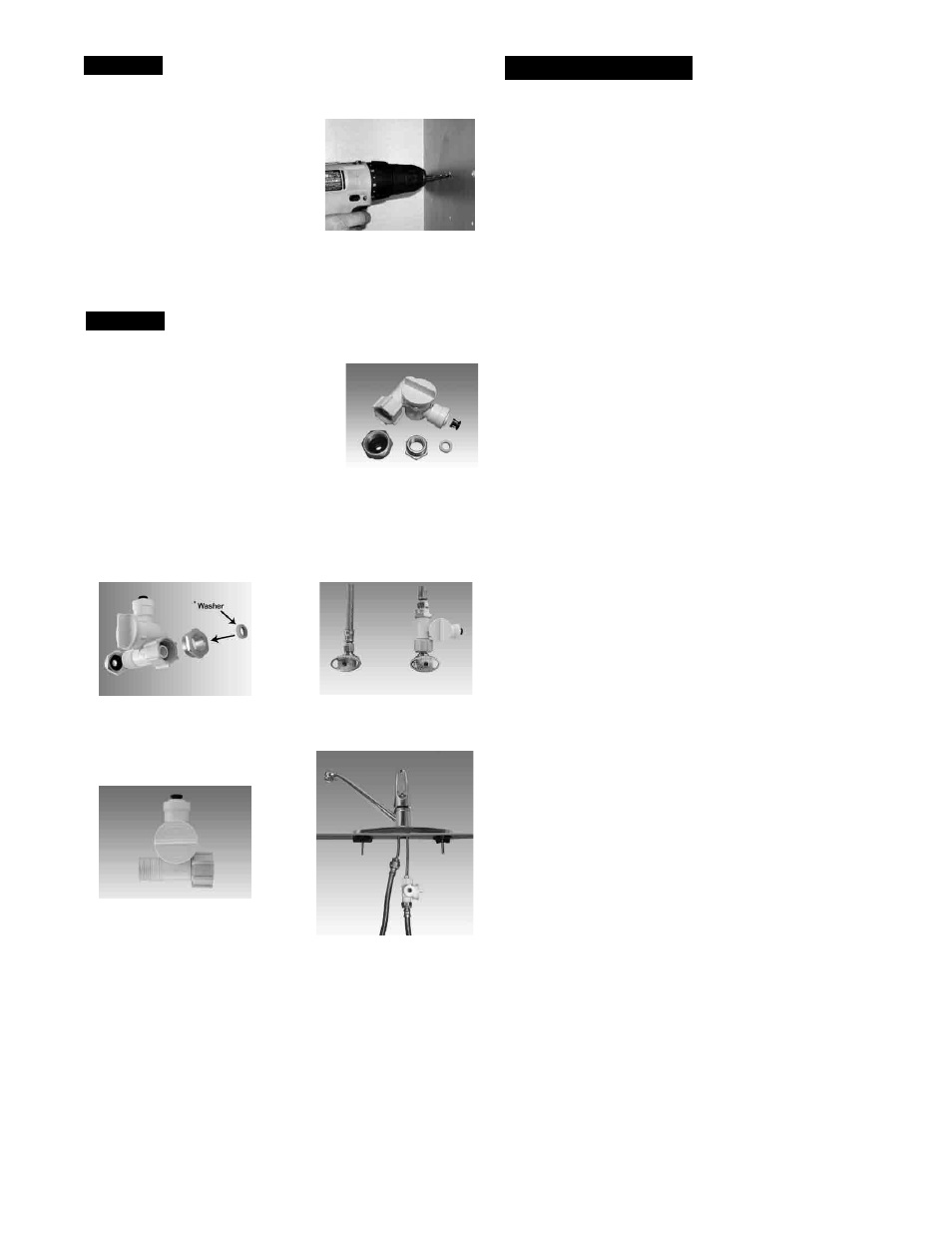
Adapt-A-Valve™ Installation
Verify contents prior to installation:
( 1 ) - Plastic Adapt-a-Valve™ & Black Collet
( 1 ) - Brass Adapter no washer
( 1 ) - Brass Adapter with black washer
( 1 ) - White rubber washer
Water supply line to the system must be from the cold water
supply line only. Hot water will severely damage your system.
WARNING: Do not use Teflon tape with the Adapt-A-Valve™.
For
3
⁄
8
" Configuration
For
1
⁄
2
" Configuration
Step A - Turn off the cold water supply to the faucet by turning the
angle stop valve completely off .
Step B - Open cold water sink faucet to relieve pressure .
Step C - Choosing the configuration that fits your plumbing, at-
tach the Adapt-A-Valve™ as illustrated in the four photos
above .
STEP 4
Hot
Supply
Cold
Supply
Hot
Supply
Cold
Supply
(With Brass Fittings)
* Insert White Washer
(Without Brass Fittings)
1
⁄
2
" Configuration