Installation, Use step 10 to install rigid drain pipe – Watts PWSPSE User Manual
Page 5
5
Installation
1. Turn off gas or electric supply to the water heater.
2. Turn off the water supply to pipes to be cut and drain the house
water pipes.
3. Open both hot and cold faucets.
4. Move the softener assembly into installation position.
• Be sure the installation surface is level and smooth.
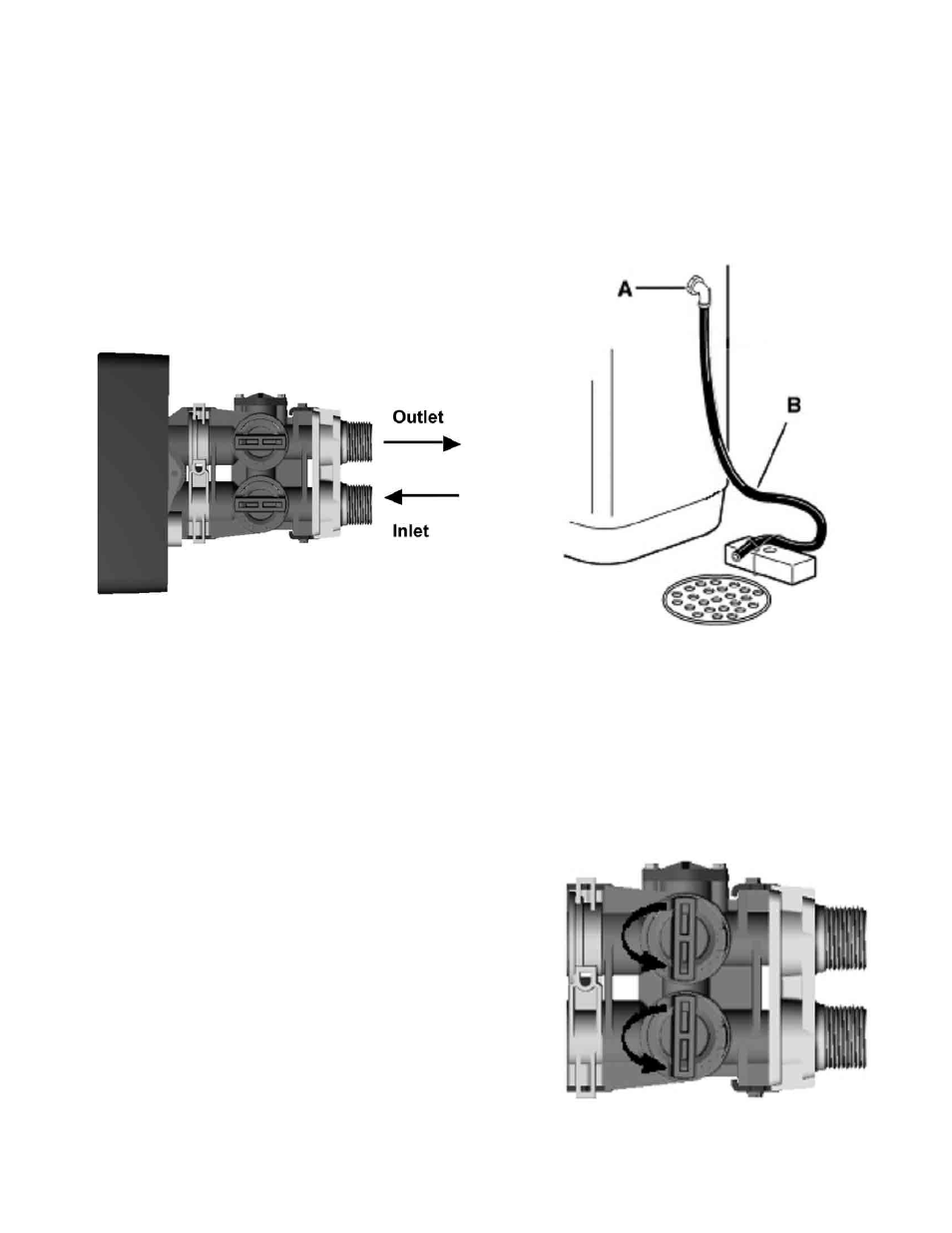
5. Plumb IN and OUT connections to and from softener.
• Be sure the incoming hard water supply is directed to the INLET
port of the valve.
• The valve body of the control is marked with arrows indicating
the proper flow direction.
• Connections are illustrated below.
Figure 2
CAUTION: If making a soldered copper installation, do all sweat
soldering before connecting pipes to the bypass valve. Torch
heat will damage plastic parts.
CAUTION: When turning threaded pipe fittings onto plastic fit-
tings, use care not to cross-thread.
CAUTION: Use Teflon tape on all external pipe threads. Do not
use pipe joint compound.
CAUTION: Support inlet and outlet plumbing in some manner
(use pipe hangers) to keep the weight off of the valve fittings.
Perform steps 6-9 to install flexible drain tube.
Skip to step 10 to install rigid drain pipe.
6. Cut the 10’ piece of
5
⁄
8
” OD black tubing in half. One section will
be used as the valve drain line. The remaining section will be used
as an overflow tube (Step 11).
7. Locate the barbed drain fitting on the back of the valve.
8. Connect and route the valve drain line.
• Use the provided tubing to attach to the valve drain fitting. Use
the included clamp to keep water pressure from blowing the
tubing off of the fitting.
9. Locate the other end of the drain tubing at a suitable drain.
• Tie or wire the tube in place at the drain point. Also provide an
air gap of at least 1
1
⁄
2
" between the end of the hose and the
drain point.
Use Step 10 to install rigid drain pipe.
10. To install a rigid drain pipe instead of tubing:
• Remove the barbed fitting from the drain port.
• Plumb
1
⁄
2
" rigid pipe from female drain port to the drain location.
Leave an air gap of at least 1
1
⁄
2
" between the end of the drain
plumbing and the drain point.
11. Take the other half of the cut tubing and attach it to the overflow
adapter elbow located on the side of the brine tank. Locate the
other end of the hose at the drain point, leaving an air gap as
shown in Figure 3.
Figure 3
12. Connect brine line from the safety valve in the brine tank to the
brine port on the valve using the
3
⁄
8
” tubing provided. Be sure to
use the brass nut, brass insert, plastic ferrule, and stainless steel
screen (included in the small parts bag) when attaching the brine
line to the valve.
13. Place bypass valve in "bypass" position as shown in figure 4.
Figure 4
A-Overflow Elbow Fitting
B-Overflow Tubing