Oil burner primary relay – Watts LFWDS User Manual
Page 3
3
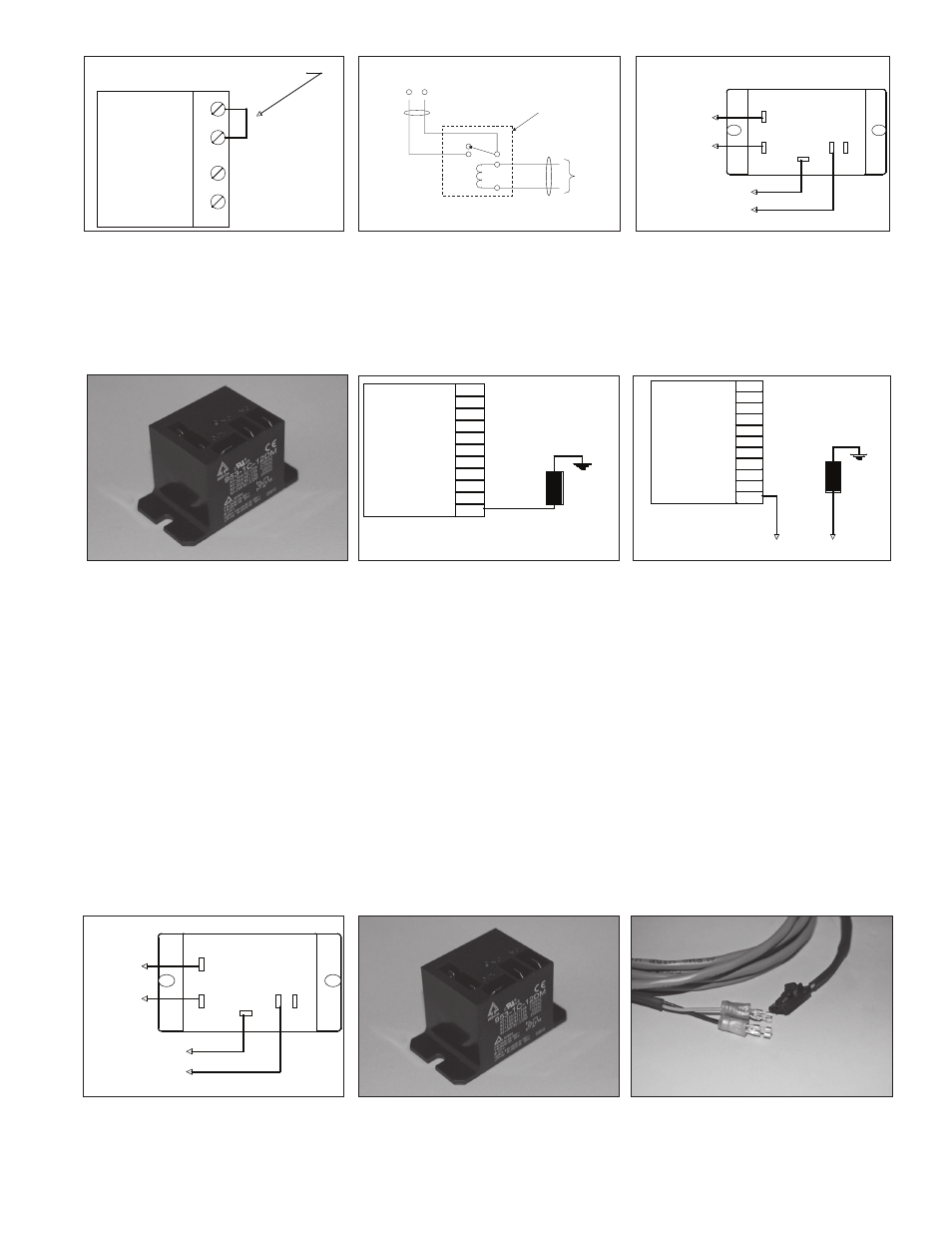
Figure 7
Figure 8
Figure 9
3. Using two conductor thermostat cable (supplied by the installer) install the spade terminals to one side of the cable and fasten termi-
nals to the other side of the cable. Connect the cable from the Power Cutout Module Terminal C (common) and NO (normally open) to
the TT terminals on the Oil burner Primary Relay as indicated in Figures 8 and 9. Install the connecting cable Figure 15 to the Power
Cutout Module terminals R1 and R2. Route the connecting cable to the Control Unit and insert the interlocking connector end to the
circuit board.
4. Proceed to Step 5 to continue installation
Spark Ignition Water Heater Installation (for Oil Fired Water Heater Installation, see page 2)
NOTE: Be certain to disconnect the circuit breaker/fuse that supplies power to the water heater. A warning label should be applied to
the panel with a warning against restoring power while work is in process.
1. Mount the Power Cutout Module as close to the electronic control module as possible.
2. Remove the wire from the Electronic Control “SPARK” terminal that goes to the Pilot Electrode Assembly from Electronic Control as
shown in Figure 11.
3. Using two-conductor thermostat cable, install the spade terminals to one side of the cable and then fasten terminals to the other
side of the cable. Connect the cable from the Power Cutout Module Figure 14 Terminal C (common) to the SPARK terminal of the
Electronic Control and NO (normally open) to the Pilot Electrode Assembly as indicated in Diagram 2, Figures 12 and 13. Note: We
have made every effort to provide all of the hardware required for a complete installation. However, the terminal connections used to
connect the Pilot Electrode Assembly to the Electronic Control vary by manufacturer, although we have included several connectors
used by leading manufacturers with your WDS, your specific mating connectors may not be included. If the required connector is
not included, it may be purchased locally at any electronic supply store. Install the Connecting Cable Figure 15 to the Power Cutout
Module terminals and R1 and R2, route the Connecting Cable to the Control Unit and insert the interlocking connector end to the
circuit board.
4. Proceed to Step 5 to continue installation.
T2
T1
Oil Burner
Primary
Relay
Remove Jumper to T T Terminals
R1
R2
C
NC
NO
To T T terminals on Oil Burner Relay
To Control Unit
POWER CUTOUT MODULE
Electronic Control
SPARK
Before
Pilot Electrode
Assembly
Electronic Control
SPARK
After
To Power
Cutout Module
Terminal
C
NO
Pilot Electrode
Assembly
Figure 11
Figure 12
Figure 13
Figure 14
Figure 15
R1
R2
C
NC
NO
To Electronic Control
To Control Unit
To Pilot Electrode
Assembly
POWER CUTOUT MODULE
Figure 10
NC
NO
R1
R2
T2
T1
POWER
CUTOUT
MODULE
OIL BURNER
PRIMARY RELAY
TO
CONTROL
UNIT
C