Bryant DURAPAC PLUS 581A User Manual
Page 41
—
41
—
8. Once desired pressure is established, set unit setting
for no call for heat, turn off main gas valve, remove
pressure-measuring device, and replace
1
/
8
-in. pipe
plug and screw cap.
X. MAIN BURNERS
For most applications, main burners are factory set and
should require no adjustment.
For applications at altitudes above 2000 ft, refer to
Tables 31 and 32 for altitude compensation.
A. Main Burner Removal
1. Shut off (field-supplied) manual main gas valve.
2. Shut off power to unit.
3. Remove gas section access panel.
4. Disconnect gas piping from gas valve inlet.
5. Remove wires from gas valve.
6. Remove wires from rollout switch.
7. Remove sensor wire and ignitor cable from IGC
board.
8. Remove 2 screws securing manifold bracket to
basepan.
9. Remove 2 screws that hold the burner assembly to
vestibule plate.
10. Lift burner/manifold assembly out of unit.
B. Cleaning and Adjustment
1. Remove burner rack from unit as described in Main
Burner Removal section above.
2. Inspect burners, and if dirty, remove burners from
rack.
3. Using a soft brush, clean burners and crossover port
as required.
4. Adjust spark gap. See Fig. 39.
5. Reinstall burners on rack.
6. Reinstall burner rack as described above.
Table 31 — Altitude Compensation (Natural Gas)
Table 32 — Altitude Compensation (LP Gas)
XI. FILTER DRIER
Replace whenever refrigerant system is exposed to
atmosphere.
XII. PROTECTIVE DEVICES
A. Compressor Protection
Overcurrent
Each compressor has internal line break motor protection.
Overtemperature
Each compressor has an internal protector to protect it
against excessively high discharge gas temperatures.
Compressor Lockout
If any of the safeties (high-pressure, low-pressure, freeze
protection thermostat, compressor internal thermostat) trip,
or if there is loss of power to the compressors, the cooling
lockout (CLO) will lock the compressors off. To reset, manu-
ally move the thermostat setting.
ELEVATION
(ft)
ORIFICE SIZE — NATURAL GAS
Low
Heat
Medium
Heat
High Heat
(6 Cell)
High Heat
(8 Cell)
0-2,000
29
30
29
29
2,000
29
30
29
29
3,000
30
31
30
30
4,000
30
31
30
30
5,000
30
31
30
30
6,000
30
31
30
30
7,000
31
32
31
31
8,000
31
32
31
31
9,000
31
32
31
31
above 10,000
32
33
32
32
ELEVATION
(ft)
ORIFICE SIZE — LP GAS
Low
Heat
Medium
Heat
High Heat
(6 Cell)
High Heat
(8 Cell)
0-2,000
35
38
35
35
2,000
36
39
36
36
3,000
36
39
36
36
4,000
37
40
37
37
5,000
37
40
37
37
6,000
38
41
38
38
7,000
39
42
39
39
8,000
40
43
40
40
9,000
41
44
41
41
above 10,000
42
45
42
42
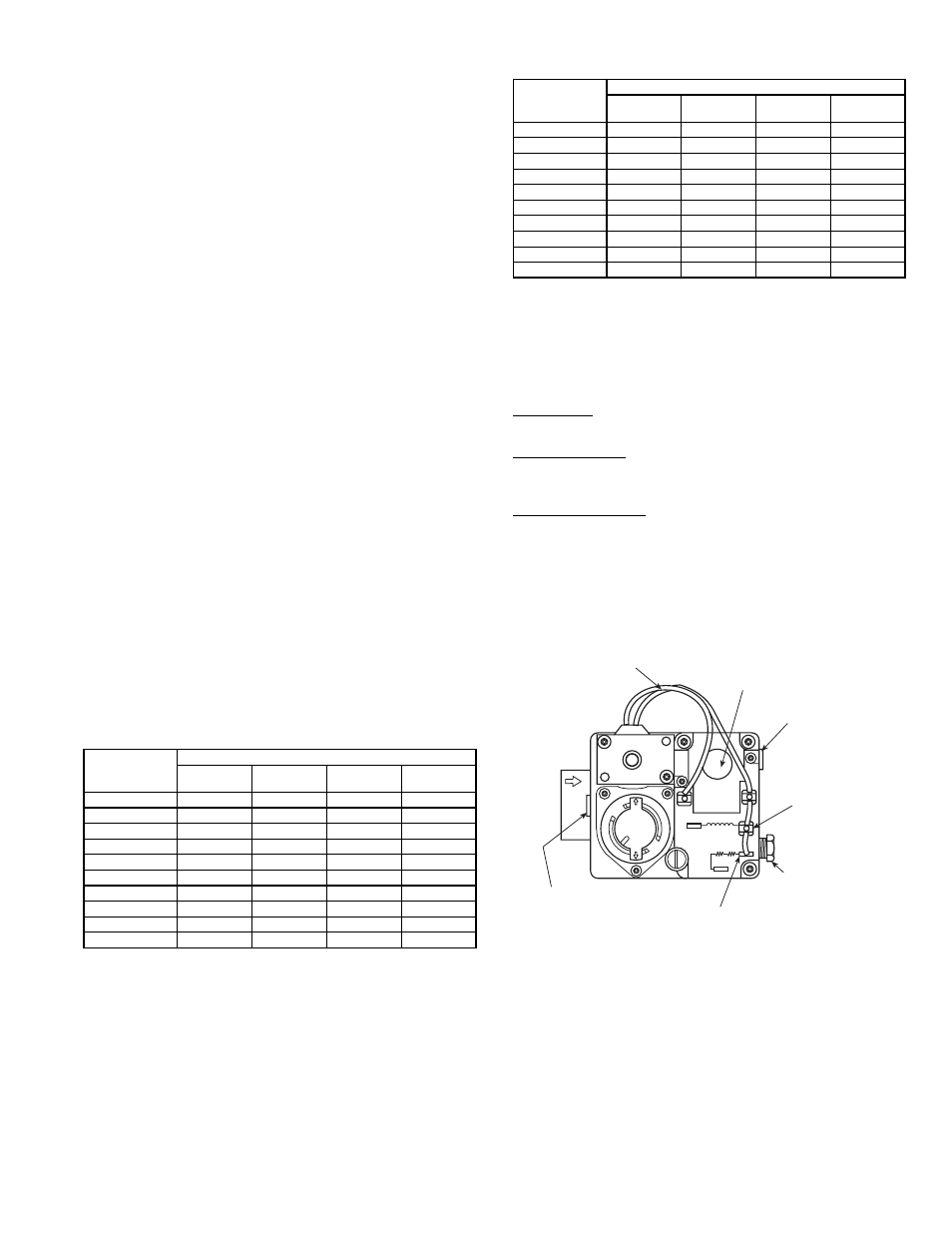
Fig. 38 — Gas Valve
OFF
ON
W-1
W-2
D-1 D-2
C1
C2
PILOT
ADJ.
INLET PRESSURE TAP
(PLUGGED)
1/8 - 27 N.P.T. THDS.
2 LEADS, #18 WIRE 1/32 INSULATION,
600V. MAX., 105
°C
REGULATOR
ADJUSTMENT SCREW
(REMOVE COVER)
OUTLET PRESSURE
TAP (PLUGGED)
1/8-27 N.P.T. THDS.
PILOT CONNECTION
FOR 1/4” O.D. TUBING
(PLUGGED)
RECEPTACLE AND
TAB COMBINATION
TERMINAL
RECEPTACLE TERMINAL