Bryant DURAPAC PLUS 581A User Manual
Page 14
—
14
—
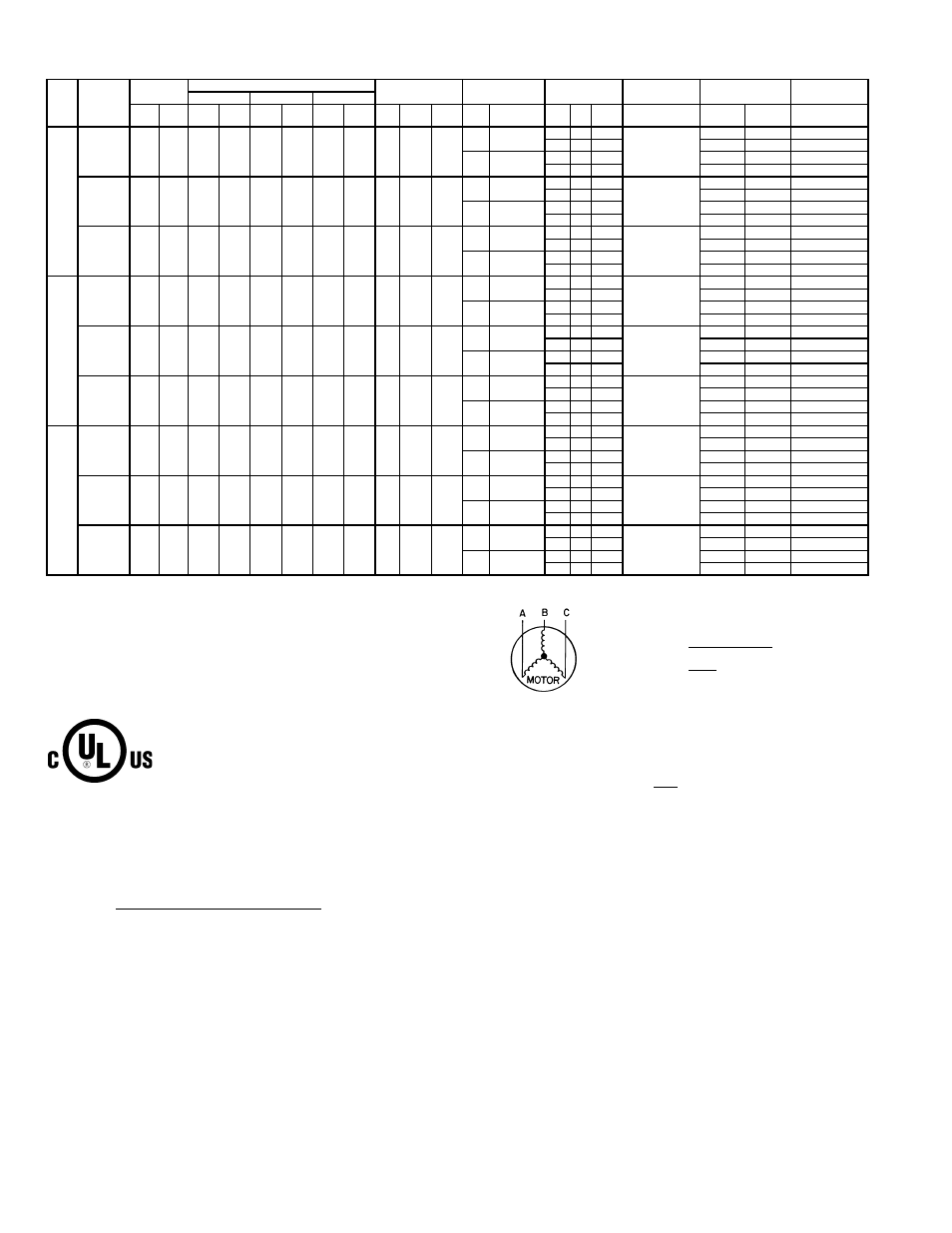
Table 4B — Electrical Data — Units With Optional Convenience Outlet
LEGEND
*Fuse or HACR circuit breaker.
NOTES:
1. In compliance with NEC requirements for multimotor and combination load equip-
ment (refer to NEC Articles 430 and 440), the overcurrent protective device for the
unit shall be fuse or HACR breaker. Canadian units may be fuse or circuit breaker.
2. Unbalanced 3-Phase Supply Voltage
Never operate a motor where a phase imbalance in supply voltage is greater than
2%. Use the following formula to determine the percent voltage imbalance.
Determine maximum deviation from average voltage.
(AB) 457 - 452 = 5 v
(BC) 464 - 457 = 7 v
(AC) 457 - 455 = 2 v
Maximum deviation is 7 v.
Determine percent voltage imbalance.
This amount of phase imbalance is satisfactory as it is below the maximum allow-
able 2%.
IMPORTANT: If the supply voltage phase imbalance is more than 2%, contact the
local electric utility company immediately.
3. The convenience outlet full load amps (FLA) are 5, 3, and 3 for 208/230, 460,
575-V units, respectively.
581A
UNIT
SIZE
NOMINAL
VOLTAGE
(3 Ph,
60 Hz)
VOLTAGE
RANGE
COMPRESSOR
OFM
IFM
POWER
EXHAUST
COMBUSTION
FAN MOTOR
POWER SUPPLY
DISCONNECT
SIZE
No. 1
No. 2
No. 3
Min
Max
RLA
LRA
RLA
LRA
RLA
LRA Qty
Hp
FLA
(ea)
Hp
FLA
Qty Hp
FLA
(ea)
FLA
MCA
MOCP*
FLA
210
208/230
187
253
16.7
130
16.7
130
22.4
184
4
0.25
1.5
3.7
10.6/ 9.6
—
—
—
0.5
83/ 82
100/100
89/ 88
2
1
5.9
95/ 94
100/100
103/101
5
16.7/15.2
—
—
—
89/ 88
100/100
96/ 94
2
1
5.9
101/ 99
110/100
110/108
460
414
506
9
70
9
70
10.7
90
4
0.25
0.7
3.7
4.8
—
—
—
0.3
42
50
45
2
1
3.1
48
50
52
5
7.6
—
—
—
45
50
48
2
1
3.1
51
60
56
575
518
633
7
55
7
55
9.3
73
4
0.25
0.7
3
3.9
—
—
—
0.24
35
40
38
2
1
2.4
40
45
43
5
6.1
—
—
—
38
45
40
2
1
2.4
42
50
46
240
208/230
187
253
22.4
184
22.4
184
22.4
184
4
0.25
1.5
5
16.7/15.2
—
—
—
0.5
101/ 99
110/100
109/107
2
1
5.9
112/111
125/125
123/121
7.5
24.2/22
—
—
—
108/106
125/125
118/115
2
1
5.9
120/118
125/125
131/129
460
414
506
10.7
90
10.7
90
10.7
90
4
0.25
0.7
5
7.6
—
—
—
0.3
48
50
52
2
1
3.1
54
60
59
7.5
11
—
—
—
52
60
56
2
1
3.1
58
60
63
575
518
633
9.3
73
9.3
73
9.3
73
4
0.25
0.7
5
6.1
—
—
—
0.24
42
50
46
2
1
2.4
47
50
51
7.5
9
—
—
—
45
50
49
2
1
2.4
50
50
55
300
208/230
187
253
47.1
245
47.1
245
—
—
6
0.25
1.5
7.5
24.2/22
—
—
—
0.5
144/142
175/175
152/150
2
1
5.9
156/154
200/200
166/163
10
30.8/28
—
—
—
151/148
175/175
160/157
2
1
5.9
163/160
200/200
173/170
460
414
506
19.6
125
19.6
125
—
—
6
0.25
0.7
7.5
11
—
—
—
0.3
62
80
66
2
1
3.1
69
80
73
10
14
—
—
—
65
80
69
2
1
3.1
72
90
77
575
518
633
15.8
100
15.8
100
—
—
6
0.25
0.7
7.5
9
—
—
—
0.24
52
60
55
2
1
2.4
57
60
60
10
11
—
—
—
54
60
57
2
1
2.4
59
60
63
FLA
— Full Load Amps
HACR — Heating, Air Conditioning and Refrigeration
IFM
— Indoor (Evaporator) Fan Motor
LRA
— Locked Rotor Amps
MCA
— Minimum Circuit Amps
MOCP — Maximum Overcurrent Protection
NEC
— National Electrical Code
OFM
— Outdoor (Condenser) Fan Motor
RLA
— Rated Load Amps
% Voltage Imbalance
= 100 x
max voltage deviation from average voltage
average voltage
EXAMPLE: Supply voltage is 460-3-60.
AB = 452 v
BC = 464 v
AC = 455 v
Average Voltage =
452 + 464 + 455
3
=
1371
3
= 457
% Voltage Imbalance = 100 x
7
457
= 1.53%