Banner T30 Series User Manual
T30 sensors - dc-voltage series, Models, Fixed-field mode overview
Self-Contained, DC-Operated Sensors
• Featuring EZ-BEAM® technology, the specially designed optics and electronics provide reliable
sensing without the need for adjustments
• “T” style plastic housing with 30 mm threaded lens in opposed, retroreflective or fixed-field
modes
• Completely epoxy-encapsulated to provide superior durability, even in harsh sensing environ-
ments rated to IP69K
• Innovative dual-indicator system takes the guesswork out of sensor performance monitoring
• Advanced diagnostics to warn of marginal sensing conditions or output overload
• 10 to 30V dc; choose SPDT (complementary) NPN or PNP outputs (150 mA max. ea.)
WARNING: Not To Be Used for Personnel Protection
Never use this device as a sensing device for personnel protection. Doing so could lead to serious
injury or death. This device does NOT include the self-checking redundant circuitry necessary to allow its
use in personnel safety applications. A sensor failure or malfunction can cause either an energized or de-
energized sensor output condition.
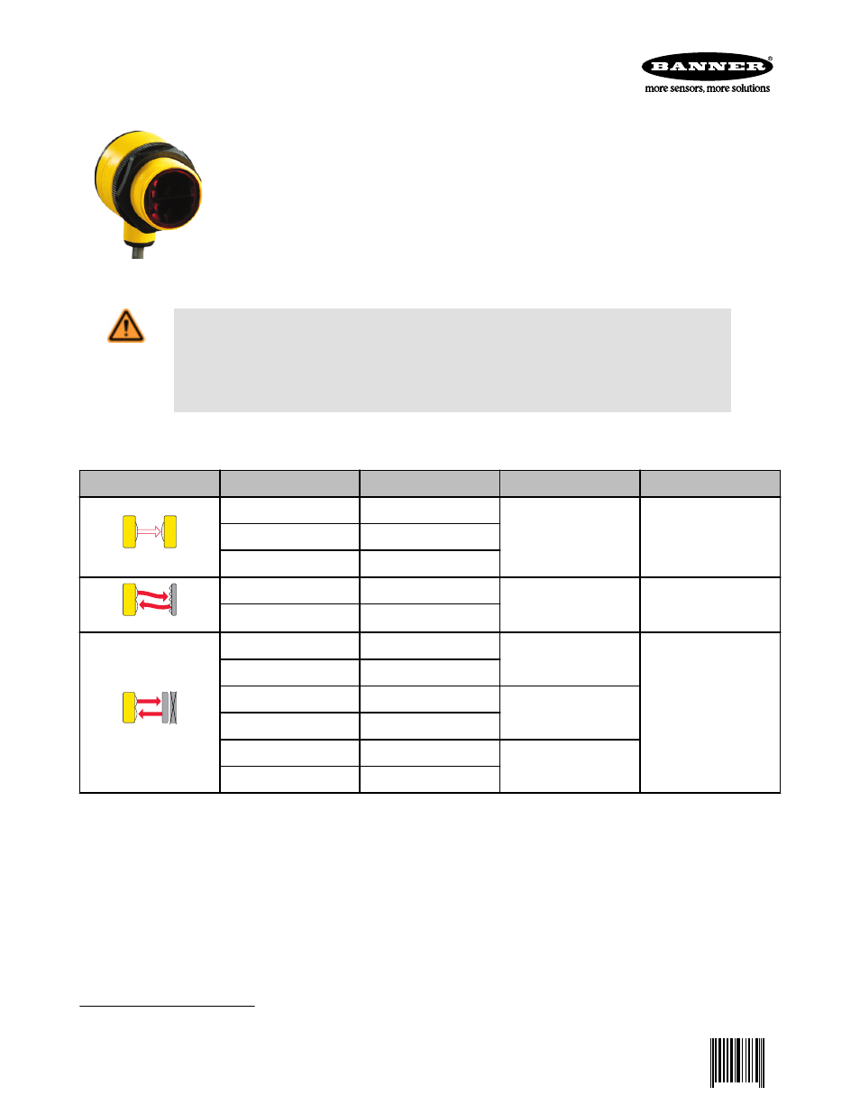
Models
Sensing Mode
Model
1
Output
Range
LED
OPPOSED
T306E
-
60 m (200 ft)
Infrared, 950 nm
T30SN6R
NPN
T30SP6R
PNP
P
POLAR RETRO
T30SN6LP
NPN
6 m (20 ft)
Visible Red, 680 nm
T30SP6LP
PNP
FIXED-FIELD
T30SN6FF200
NPN
200 mm (8 in) cutoff
Infrared, 880 nm
T30SP6FF200
PNP
T30SN6FF400
NPN
400 mm (16 in) cutoff
T30SP6FF400
PNP
T30SN6FF600
NPN
600 mm (24 in) cutoff
T30SP6FF600
PNP
Fixed-Field Mode Overview
T30 Series self-contained fixed-field sensors are small, powerful, infrared diffuse mode sensors with far-limit cutoff (a type of background
suppression). Their high excess gain and fixed-field technology allow detection of objects of low reflectivity, while ignoring background
surfaces. The cutoff distance is fixed. Backgrounds and background objects must always be placed beyond the cutoff distance.
Fixed-Field Sensing – Theory of Operation
The T30FF compares the reflections of its emitted light beam (E) from an object back to the sensor’s two differently aimed detectors, R1
and R2. See
on page 2. If the near detector's (R1) light signal is stronger than the far detector's (R2)
light signal (see object A in the Figure below, closer than the cutoff distance), the sensor responds to the object. If the far detector's (R2)
light signal is stronger than the near detector's (R1) light signal (see object B in the Figure below, beyond the cutoff distance), the sensor
ignores the object.
1
Standard 2 m (6.5 ft) cable models are listed. To order 9 m (30 ft) cable: add suffix W/30 (for example, T306EW/30). To order 4-pin Euro-style QD models: add suffix Q (for example,
T306EQ). A model with a QD connector requires a mating cable; see
on page 7.
T30 Sensors - DC-Voltage Series
P/N 121524 Rev. A
2/13/2013
0 121524
1