Figure 5. object beyond cutoff - problem, Figure 6. object beyond, Cutoff - solution – Banner T30 Series User Manual
Page 3: Figure 6. object beyond cutoff - solution, Specifications, Color sensitivity
Fixed
Sensing
Field
Cutoff
Distance
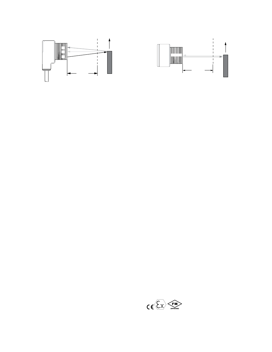
R1 = Near Detector
R2 = Far Detector
E = Emitter
T30FF
R1
E
R2
Reflective
Background
or
Moving Object
A reflective background object in this position or moving across the sensor face
in this axis and direction may cause false sensor response.
Figure 5. Object Beyond Cutoff - Problem
E = Emitter
R2 = Far Detector
R1 = Near Detector
T30FF
E, R2, R1
Fixed
Sensing
Field
Cutoff
Distance
Reflective
Background
or
Moving Object
A reflective background object in this position or moving across the sensor face
in this axis will be ignored.
Figure 6. Object Beyond Cutoff - Solution
Color Sensitivity
The effects of object reflectivity on cutoff distance, though small, may be important for some applications. It is expected that at any given cutoff setting, the actual cutoff
distance for lower reflectance targets is slightly shorter than for higher reflectance targets. This behavior is known as color sensitivity.
For example, an excess gain of 1 for an object that reflects 1/10 as much light as the 90% white card is represented by the horizontal graph line at excess gain = 10. An
object of this reflectivity results in a far limit cutoff of approximately 130 mm (5.1 in); thus 130 mm represents the cutoff for this sensor and target.
These excess gain curves were generated using a white test card of 90% reflectance. Objects with reflectivity of less than 90% reflect less light back to the sensor, and thus
require proportionately more excess gain in order to be sensed with the same reliability as more reflective objects. When sensing an object of very low reflectivity, it may be
especially important to sense it at or near the distance of maximum excess gain.
Specifications
Supply Voltage and Current
5 to 30V dc (provided by the amplifier to which the sensor is connected)
Output
Constant current output; ≤1.2 mA in the dark condition and ≥2.1 mA in
the light condition
Output Response Time
10 ms on/off (does not include amplifier response)
Sensing Beam
Infrared (880 nm)
Cutoff Distance
150 mm (5.9 in), referenced to a 90% reflectance white test card. See
excess gain curve.
Indicators
Red indicator LED on rear panel turns on when the sensor sees a light
condition.
Construction
Yellow PBT enclosure, PBT rear cover. Acrylic lens. M30xl,5 threaded
lens housing with two mounting nuts supplied. Meets NEMA standards 1,
2, 3, 3S, 4, 4X, 6, 6P, 12, and 13. IEC IP67.
Connections
2 m (6.5 ft) attached PVC covered cable or 4-pin Euro-style quick-dis-
connect (QD) fitting, depending on model. QD cable must be purchased
separately.
Operating Conditions
Temperature: −40 °C to +70 °C (−40 °F to +158 °F)
Vibration and Mechanical Shock
Meets Mil. Std. 202F requirements. Method 201A (Vibration: frequency
10 to 60 Hz max., double amplitude 0.06-inch, maximum acceleration
10G). Method 213B conditions H & I (Shock: 75G with unit operating;
100G for non-operation).
Design Standards
ATEX (European)
EN 60079-0, EN 60079-11, EN 60079-26
Canadian
CAN/CSA C22.2 No. 0-M91, No. 142-M1987, No.157-92, No. 1010.1,
E60079-0, E60079-11
United States
FM Class 3600, 3610, and 3810, ANSI/ISA 61010-1 (82.02.01),
ANSI/ISA 60079-0, 60079-11, and 60079-26
Approvals
ATEX (European)
II 1 G Ex ia IIC T6 Ta = -40 °C to 70 °C - 13321; Entity
FM12ATEX0094X
Entity Parameters: V
Max
= 30 V, I
Max
= 35 mA, C
i
= 0, L
i
= 0
Canada
Intrinsically safe for Class I, II and III, Division 1, Groups A, B, C, D, E, F
and G T6 Ta = -40 °C to 70 °C - 13321; Entity
Intrinsically safe for Class I, Zone 0 Ex ia Group IIC T5 Ta = -40 °C to 70
°C
Entity Parameters: V
Max
= 30 V, I
Max
= 350 mA, C
i
= 0, L
i
= 0
United States
Intrinsically safe for Class I,II and III, Division 1, Groups A, B, C, D, E, F
and G T6 Ta = -40 °C to 70 °C - 13321; Entity
Intrinsically safe for Class I, Zone 0 AEx ia Group IIC T5 Ta = -40 °C to
70 °C
Entity Parameters: V
Max
= 15 V dc, I
Max
= 35 mA, Pi = 0.131 W, C
i
= 0.3
μF, L
i
= 0 mH.
Certifications
T30 Series NAMUR Fixed-Field Sensors
P/N 041685 Rev. B
www.bannerengineering.com - tel: 763-544-3164
3