Qmt42 series fixed-field sensors, Qmt42 series fixed-field mode specification – Banner QMT42 Series Fixed-Field Sensors User Manual
Page 3
QMT42 Series Fixed-Field Sensors
page
3
Banner Engineering Corp. • Minneapolis, U.S.A.
Website: http://www.baneng.com • Tel: 612.544.3164
Sensing Beam
Cutoff Point Tolerance
±10% of nominal cutoff distance
Supply Protection Circuitry
Protected against reverse polarity and transient voltages
Output Configuration
SPDT (complementary) solid-state dc switch; choose NPN (current sinking) or PNP (current sourcing) models.
Light operate: N.O. output conducts when the sensor sees its own modulated light
Dark operate: N.C. output conducts when the sensor sees dark
Output Rating
100 mA maximum (each output)
OFF-state leakage current: < 5 microamps at 30V dc
ON-state saturation voltage: < 1V at 10 mA dc; < 1.5V at 100 mA dc
Output Protection Circuitry
Protected against false pulse on power-up and continuous overload or short-circuit of outputs
Overload trip point
≥
150mA, typical, at 20ºC
Output Response Time
1 millisecond on and off
NOTE: 100 millisecond delay on power-up; outputs are non-conducting during this time
Indicators
Two LEDs: Green and Yellow
GREEN glowing steadily
= power to sensor is ON
GREEN flashing
= output is overloaded
YELLOW glowing steadily = light is sensed; normally open output ON
YELLOW flashing
= marginal excess gain (1-1.5x) in light condition
Repeatability of Response
250 microseconds
Certifications
Construction
Housings are die-cast zinc alloy with black acrylic polyurethane finish; lenses are acrylic
Environmental Rating
IP67; NEMA 6
Connections
2 m (6.5') or 9 m (30') attached cable, or 4-pin Euro-style quick-disconnect fitting; cables for QD models
are purchased separately
Operating Conditions
Temperature: -20º to +55ºC (-4º to 131ºF)
Maximum relative humidity: 90% at 50ºC (non-condensing)
Sensing Hysteresis
Less than 5% of cutoff distance - 2000 mm models
Less than 4% of cutoff distance - 1500 mm models
Less than 3% of cutoff distance - 1000 mm models
Less than 2% of cutoff distance - 750 mm models
Less than 1% of cutoff distance - 500 mm models
Infrared, 880 nm
Supply Voltage and Current
10 to 30V dc (10% maximum ripple) at less than 40 milliamps
QMT42 Series Fixed-Field Mode Specification
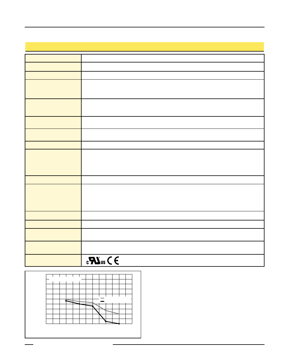
Interpretation of Cutoff Point Deviation Curve
The percentage of deviation indicates a change in the cutoff
point for either 18% gray or 6% black targets, relative to the
cutoff point for a 90% reflective white test card.
As an example, the cutoff point decreases 10% for a 6%
reflectance black target when the cutoff point is 2000
millimeters (79") using a 90% reflectance white test card. In
other words, the cutoff point for the black target is 1800
millimeters (71").
0
-8
-10
-6
-4
-2
0
+2
+4
+6
+8
+10
500 mm
(20 in)
750 mm
(30 in)
1000 mm
(39 in)
1500 mm
(59 in)
Cutoff Point Variation Relative to 90% Reflectance White Test Card
Percent
Deviation
2000 mm
(79 in)
18% Gray Color Sensitivity
6 % Black Color Sensitivity
Cutoff Point Deviation