Banner U-GAGE ULTRA-BEAM Series User Manual
Page 5
3) Based on your choice in step 1, follow the appropriate adjustment procedure below:
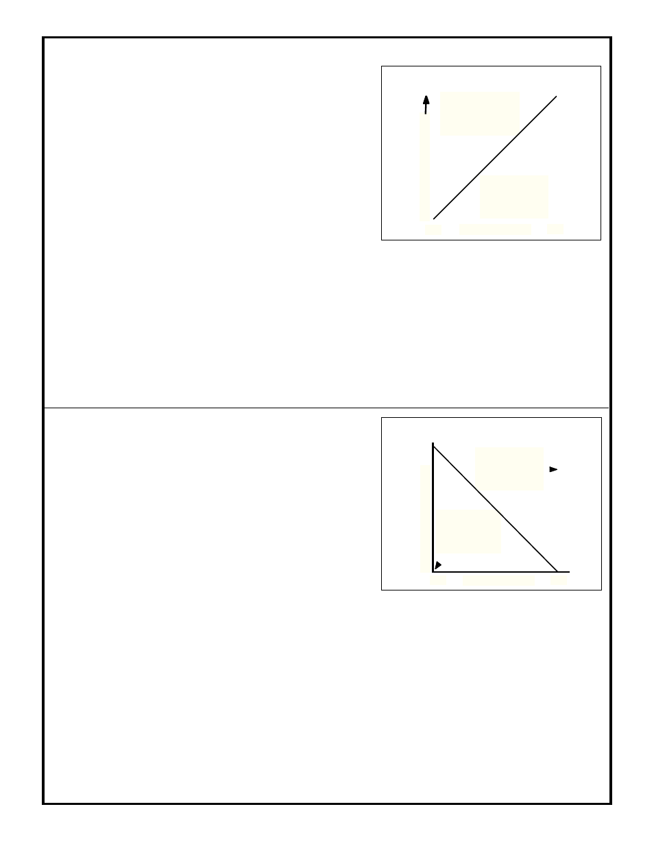
FIGURE H: Example; 5' deep window, positive slope
a) Adjustment procedure for positive slope analog output
1) Make sure that the slope select jumper clip behind the front panel of the sensor
is set for positive slope (see figure G). Remove the nylon screws covering the NULL
and SPAN controls.
2) Connect the 0 to 20mA dc sinking output of the ULTRA-BEAM to a milliammeter
(or the 0 to +10V dc sourcing output to a voltmeter) or to another instrument to be
used for readout, as shown in Figures J, K, L, and M. Connect the sensor's power
supply wires to an appropriate power supply. Double-check the connections and
switch on the power. If the sensor is receiving power, a ticking noise will be heard
from the sensor.
3) Positive slope means that the analog value of the sinking or sourcing output
increases as sensor-to-object distance increases, and decreases as that distance
decreases. The minimum and maximum current or voltage limits can be placed to
define a sensing window 12" to 18'4" deep anywhere within the 20" to 20' overall
sensor range. In the example at the right, a 5' deep window has been placed with its
near edge at 10' and its far edge at 15'. The NULL control sets the position of the
near (minimum current or voltage) end of the slope; the SPAN control sets the
position of the far (maximum current or voltage) end of the slope.
4) Set your own sensing window as follows:
a) With a target object at the near end of the window, adjust the NULL control to
just obtain a reading of 0.0mA (or your instrument's minimum current require-
ment) or 0.0V dc (or your instrument's minimum voltage requirement) on the
readout instrument. The red LED on top of the sensor should pulse in proportion
to the analog output. (If the NULL control is set for 0.0mA or 0.0V dc, there will
be no pulsing.) Remove the target.
b) Place the target at the far end of the window. Adjust the SPAN control for a
reading of 20mA (or your instrument's maximum current requirement) or +10V
dc (or your instrument's maximum voltage requirement) on the readout instru-
ment. The LED indicator should pulse at a rate propor-
tional to the analog output. Remove the target.
c) Confirm your settings by reintroducing the target at the
near edge of the sensing window. Move the target outward
in steps along the sensing axis. The analog output should
increase proportionately beginning with its set minimum,
and reach it's set maximum at the far edge of the sensing
window, at which point the LED indicator should again
pulse at its highest rate.
APPLICATION NOTE: with the sensor set for positive
slope, the sensing window may be easily shifted along the
sensing axis by moving the NULL setting. The depth of
the window will remain constant.
Max. output at 15';
set by SPAN control;
corresponds to
maximum current or
voltage output
Sensing Window
10ft
15ft
Min. output at 10';
set by NULL control;
corresponds to minimum
current or voltage
output
A
na
log Ou
tpu
t In
crease
s
b) Adjustment procedure for negative slope analog output
FIGURE I: Example; 5' deep window, negative slope
Min. output at 15';
set by SPAN control;
corresponds to
minimum current or
voltage output
Max. output at 10';
set by NULL control;
corresponds to
maximum current or
voltage output
A
na
log Ou
tpu
t In
crease
s
Sensing Window
10ft
15ft
a) With a target object at the near end of the window, adjust the NULL control to
just obtain a reading of 20mA (or your instrument's maximum current require-
ment) or +10V dc (or your instrument's maximum voltage requirement) on the
readout instrument. The red LED on top of the sensor should pulse in proportion
to the analog output. Remove the target.
b) Place the target at the far end of the window. Adjust the SPAN control for a
reading of 0.0mA (or your instrument's minimum current requirement) or 0.0V dc
(or your instrument's minimum voltage requirement) on the readout instrument.
1) Make sure that the slope select jumper clip behind the front panel of the sensor
is set for negative slope (see figure G). Remove the nylon screws covering the NULL
and SPAN controls.
2) Connect the 0 to 20mA dc sinking output of the ULTRA-BEAM to a milliammeter
(or the 0 to +10V dc sourcing output to a voltmeter) or to another instrument to be
used for readout, as shown in Figures J, K, L, and M. Connect the sensor's power
supply wires to an appropriate power supply. Double-check the connections and
switch on the power. If the sensor is receiving power, a ticking noise will be heard
from the sensor.
3) Negative slope means that the analog value of the sinking or sourcing output
decreases as sensor-to-object distance increases, and increases as that distance
decreases. The minimum and maximum current or voltage limits can be placed to
define a sensing window 12" to 18'4" deep anywhere within the overall 20" to 20'
sensor range. In the example at the right, a 5' deep window has been placed with its
near edge at 10' and its far edge at 15'. The NULL control sets the position of the
near (maximum current or voltage) end of the slope; the SPAN control sets the
position of the far (minimum current or voltage) end of the slope.
4) Set your own sensing window as follows:
The LED indicator should pulse at a rate proportional to
the analog output. (If the SPAN control is set for 0.0mA
or 0.0V dc, there will be no pulsing.) Return the target to
the near end of the window (same position as in step "a")
and "fine-tune" the NULL setting by repeating step "a".
d) Confirm your settings by reintroducing the target at the
far edge of the sensing window. Move the target inward in
steps along the sensing axis. The analog output should
increase proportionately beginning with its set minimum,
and reach it's set maximum at the near edge of the sensing
window, at which point the LED indicator should again
pulse at its highest rate.