Dimensions with smbls 3-axis mounting bracket, Spare parts identification, Wiring – Banner MULTI-BEAM Series User Manual
Page 2: Alignment
Then, while holding the receiver and watching its alignment indicator
LED, move the receiver up-down and left-right, including angular posi-
tion, to locate the center of the beam. The center of the beam corre-
sponds to the strongest received signal level (fastest receiver LED
indicator pulse rate).
If the sensing area is large, reduce the sensitivity of the receiver (remove
the white nylon screw and turn the control counterclockwise) to shrink the
area. Note that this is a 15-turn control. If the emitter-receiver distance
will change during use, perform the alignment at the greatest expected
separation distance. Mount the receiver securely in the center of the beam,
and increase the
SENSITIVITY
control to maximum (15 or more full turns
fully clockwise).
Final checkout: The red LED indicator on the R1T3 receiver should be
"on" with power applied to correctly aligned units, and should go "off"
when current is applied to the modulator input (terminal #3) of the EM3T-
1M transmitter.
The light/dark operate selection jumper on the R1T3's logic module
reverses the polarity of the receiver's data stream output.
Wiring
System power: Power the sensors with 10-30V dc at terminals #1 and
#2 of each power block, observing polarity. Total current requirement is
130 mA per sensor pair, exclusive of load.
Emitter gate input: Install a suitable series resistor to limit current to 10-
30 mA. Observe polarity when connecting the gating signal.
Receiver output: The output of the receiver at terminal #3 can sink up to
250 mA at 10-30V dc. If a current sourcing output is required, substitute
power block model PBP, or assembled receiver model R1P3.
Alignment
Reliable operation of the MULTI-BEAM Optical Data
Transmitter System requires the maintenance of alignment between the
transmitter and receiver units. The model SMBLS 3-axis mounting
bracket (see above) is recommended for ease and reliability of alignment.
After all wiring has been completed and checked, align the optical data
transmitter system components. First, mount the emitter in place. Apply
power to both units. Align the units to each other as best you can "by eye".
Installation and Alignment
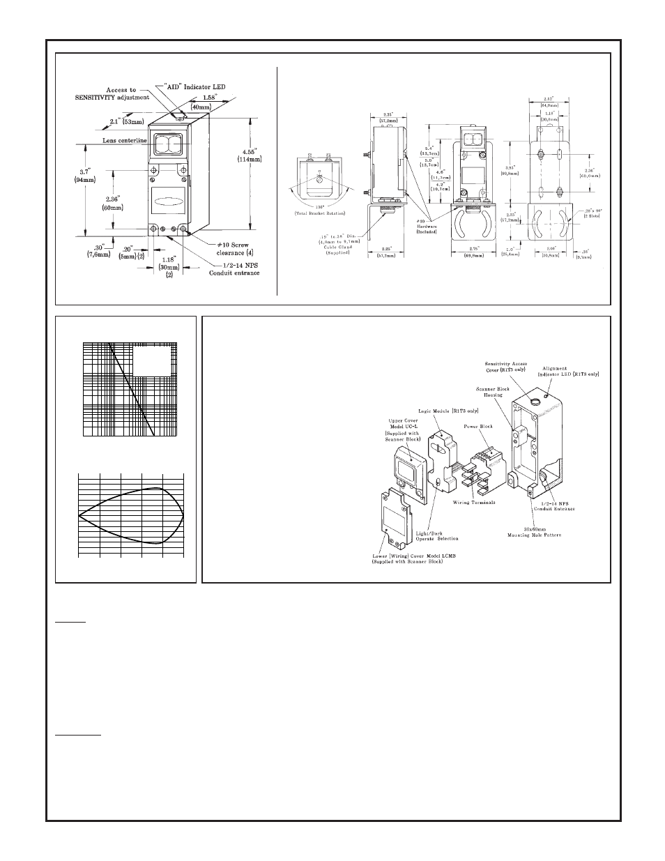
Dimensions, R1T3 Receiver*
*EM3T-1M dimensions identical, except no indicator LED or
SENSITIVITY adjustment.
Banner Engineering Corp. 9714 Tenth Ave. No. Minneapolis, MN 55441 Telephone: (612) 544-3164 FAX (applications): (612) 544-
3573
Dimensions with SMBLS 3-axis Mounting Bracket
Excess Gain Curve
Beam Pattern
40
0
0
I
N
C
H
E
S
OPPOSED DISTANCE--FEET
80
120
160
200
20
40
60
20
40
60
10
1
DISTANCE
100
1000
1 FT
10 FT
100 FT
1000FT
Excess Gain,
MULTI-BEAM
Optical Data
Transmitter
System
E
X
C
E
S
S
G
A
I
N
I
Spare Parts Identification
The modular parts of the Optical Data Trans-
mitter System may be ordered individually.
R1T3 Receiver:
SBR1 Scanner Block (includes covers)
UC-L upper cover (includes lens)
LCMB lower cover (includes screws)
PBT* 10-30V dc Power Block with
sinking (NPN) output
LM3 Logic Module (light or dark operate)
*For sourcing (PNP) output, substitute power
block model PBP.
EM3T-1M Emitter:
SBEM3 Scanner Block (includes covers)
UC-L upper cover (includes lens)
LCMB lower cover (includes screws)
PBT-1M 10-30V dc Power Block with
opticaly-coupled emitter gate.
NOTES: Logic module not required for
emitter. Emitter scanner block connects to
emitter power block via 4-pin connector sup-
plied with the scanner block.