Hookup and timing logic selection, Dimensions, q85 polarized retro sensors – Banner Q85 Series User Manual
Page 2
Banner Engineering Corp. 9714 10th Avenue No., Minneapolis, MN 55441 Telephone: (612) 544-3164 FAX (applications): (612) 544-3573
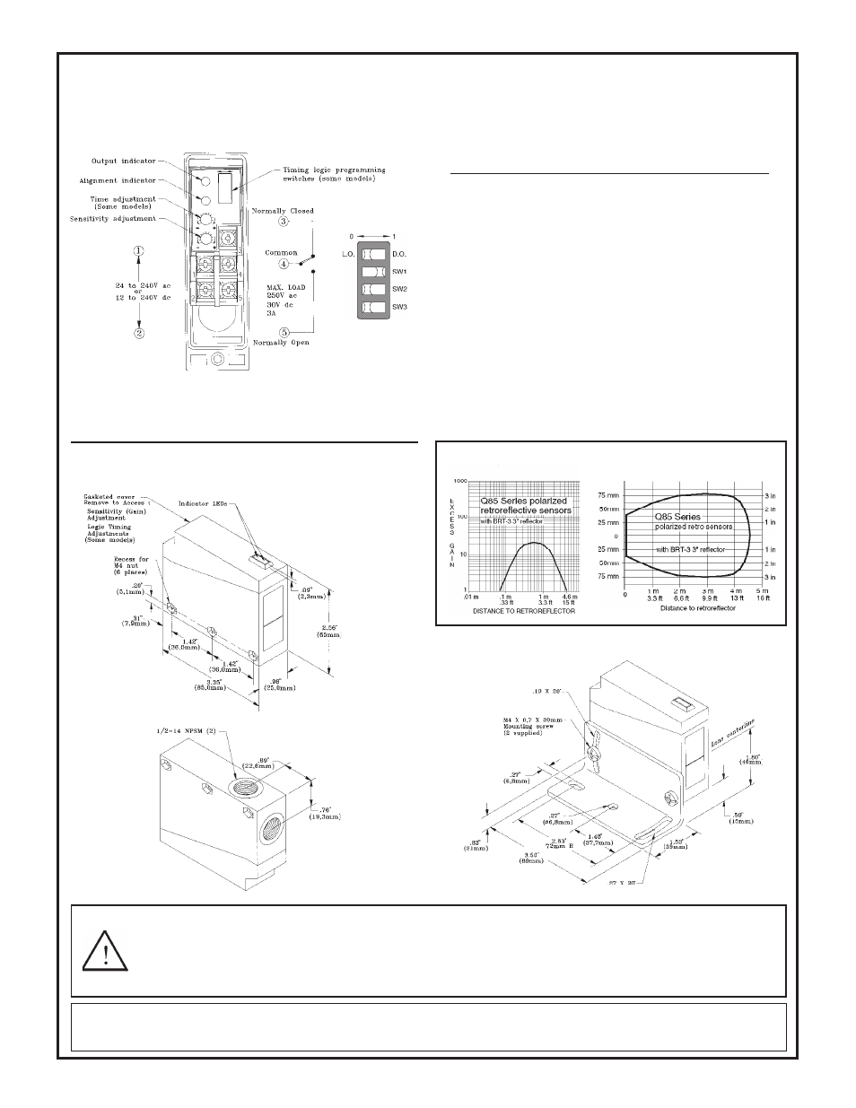
Hookup to the ac line and the external load is made at the five terminals
inside the wiring chamber (see drawing below). There is no polarity for
power supply hookup. Output is an SPDT electromechanical relay.
The output timing logic function (on sensor models with T9 model
number suffix) is selected at the timing logic programming switches,
according to the table (right). The output timing logic delays are set at
Timing logic
programming
switch detail:
With the light/dark operate switch (T9 models) set to light operate
(L.O.), the sensor's electromechanical output relay is energized when
the sensor sees the reflection of its own modulated light. In the dark
operate (D.O.) position, the output is energized when the sensor does
not see the reflection of its modulated light source.
Sensor sensitivity is set at the single-turn sensitivity adjustment po-
tentiometer.
Hookup and timing logic selection
Beam Pattern
Top view
Dimensions, Q85 polarized retro sensors
Shown with mounting bracket
(included)
Bottom view
Excess Gain Curve
WARNING
This photoelectric presence sensor does NOT include the self-checking redundant circuitry necessary to allow its use in personnel safety
applications. A sensor failure or malfunction can result in either an energized or a de-energized sensor output condition.
Never use this product as a sensing device for personnel protection. Its use as a safety device may create an unsafe condition which could lead to serious
injury or death. Only MACHINE-GUARD and PERIMETER-GUARD Systems, and other systems so designated, are designed to meet OSHA and ANSI
machine safety standards for point-of-operation guarding devices. No other Banner sensors or controls are designed to meet these standards, and they
must NOT be used as sensing devices for personnel protection.
WARRANTY: Banner Engineering Corporation warrants its products to be free from defects for one year. Banner Engineering Corporation will repair or replace, free of charge,
any product of its manufacture found to be defective at the time it is returned to the factory during the warranty period. This warranty does not cover damage or liability for the
improper application of Banner products. This warranty is in lieu of any other warranty either expressed or implied.
Logic function
Switch: SW1
SW2
SW3
ON and OFF delays (both)
0
0
0
ON delay (only)
0
0
1
OFF delay (only)
0
1
0
No delays
0
1
1
ON delayed one-shot
1
0
0
ON delayed limit timer
1
0
1
One-shot
1
1
0
Limit timer
1
1
1
the single-turn time adjustment potentiometer. When the timing function
involves more than one time (as in ON and OFF delay, ON-delayed
one-shot, and ON-delayed limit timer functions), the potentiometer sets
both times to the same value.