Specifications, opbx2 series power blocks, Power block programming information, Address number – Banner OMNI-BEAM Series User Manual
Page 2: Power block output status, Module mode
Banner Engineering Corp., 9714 10th Ave. No., Minneapolis, MN 55441 Telephone: (763) 544-3164 FAX (applications): (763) 544-3573
Specifications, OPBX2 Series power blocks
Models:
OPBX2 (attached 6-1/2 foot cable), or OPBX2QD (5-pin
minifast™ QD; requires Banner XQDC12 Quick Disconnect cable).
Supply voltage:
+9 to 12V dc; 80 mA per sensor at 12V dc (power
block output conducting).
Clock requirements:
Use APC SPX-CLK Series clock module,
available from APC.
SPX-CLK10K (10 kilohertz)
SPX-CLK64K (64 kilohertz)
SPX-CLK32K (32 kilohertz)
SPX-CLK100K (100 kilohertz)
One clock module is required per stand-alone network.
Wiring information:
Use only Seriplex-compatible cable.
Standard OPBX2 model has a 6-1/2 foot attached unterminated
cable.
QD model OPBX2QD requires Banner XQDC12 mating QD cable.
QD cable length is 12 feet; 5-pin minifast™ female sensor connector
on one end with other end unterminated.
Unterminated sensor extension cable (XECS Series) is available.
For bus cable, use Banner XECT Series cable.
Banner PHOTOBUS™ BUS DEPOT™ junction boxes provide a
convenient means of connecting PHOTOBUS™ sensors to a SERI-
PLEX
®
bus. Model BD6T1 (product data sheet 34146) enables parallel
connection of up to six I/O devices on a continuing bus. Model BD2T2
enables parallel connection of two bus branches or two I/O devices on
a continuing bus (see product data sheet 34437).
Programming cable:
Model XPC1A, available from Banner.
Jumper plug is model XPJ1, and is supplied with the power block.
See discussion at left for more information.
Programming is done via the APC Hand-held Programmer.
OPBX2 Series Control Byte
Module mode: 0 = stand-alone, 1 = host processor
Unused (must be set to 1)
Unused (must be set to 1)
Unused, setting is ignored
Unused, setting is ignored
Unused, setting is ignored
ALARM
* output (B) status: set to 0
LOAD
* output (A) status: set to 0
7 6 5 4 3 2 1 0
Bits:
1 1
*OMNI-BEAM Standard sensor heads. When E Series sensor heads are used, the
normally open LOAD output from the sensor head appears simultaneously on both
A and B power block outputs.
1 1
Figure 3. OPBX2 Series control byte
Connection to a stand-alone network
OMNI-BEAM OPBX2 Series PHOTOBUS™ Power Block
Modules are connected in parallel with each other (and with the
devices they are to control) on a Seriplex network. Possible network
configurations include ring, loop-back, star, or bus. Power blocks
are available with either attached cable or a built-in QD (Quick
Disconnect) connector. QD models require Banner XQDC Series
cable, sold separately.
Power block programming information
The programming information presented in this data sheet is in
addition to the programming procedure details given in the Pro-
gramming Seriplex™ I/O Modules section of the APC Seriplex
Programmable Control System Instruction Manual provided with
the APC hand-held programmer. Read and understand both the APC
manual and the information below before attempting to program
the OPBX2 Series Power Block.
OPBX2 Series Power Blocks are programmed, by the user, for
three attributes (details below). The APC hand-held programmer
connects to the programming port of the power block using a pro-
gramming cable (model XPC1A, available from Banner, see Figure
2 for connection information). Programming is typically done at
initial system setup, and may be done either before or after the
power block is wired into the Seriplex network. Since EEPROMs
retain their programmed information in spite of power failures, they
need be reprogrammed only if the usage of the sensor within the
network changes. The three programmable attributes are:
Address number:
The load and alarm outputs from Standard
OMNI-BEAM Sensor heads are separate and distinct, and are
addressed separately as channel A (load) and channel B (alarm).
If the alarm signal is not required, assign channel B to an unused
address. When E Series Sensor Heads are used, the normally open
load output from the sensor head appears simultaneously on both
power block outputs (A and B). Addresses are decimal values in
the range of 001 through 255, and need not be assigned in numerical
order. (NOTE: Care should be taken when choosing addresses.
The Seriplex
®
system will logically "OR" signals with the same
address. See Seriplex
®
literature for more information.)
Power block output status:
Bits 6 and 7 of the control byte
(Figure 3) are used to configure channel B and channel A power
block outputs (respectively). Setting these bits to "1" inverts the
signal within the power block. It is recommended that these bits
be set to "0". Signal inversions may instead be performed via a
dip switch inside the sensor head.
Module mode:
Bit 0 in the control byte (Figure 3) is used to
select the power block's mode of operation. Set this bit to "0" if
there is no host processor connected (stand-alone mode). If output
data will be read from the data line as set by a host processor , set
this bit to "1".
Bits 1 and 2 are test bits which are not used in normal opera-
tion, and must be set to "1".
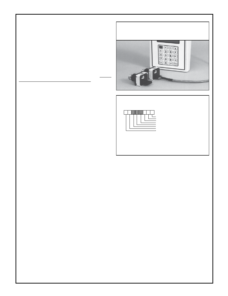
Figure 2.
Power block with jumper plug in operating posi-
tion (left), and with jumper plug removed and program-
ming cable attached (right); APC hand-held programmer in
background.