Metrohm 752 Pump Unit User Manual
Page 15
2 Installation
752 Pump Unit
12
16
16
17
17
18
18 19
19
44
55
19
19 17
17
90
90//93
93
77
20
20
20
20
16
16 20
20
22
22 23
23 20
20
21
21
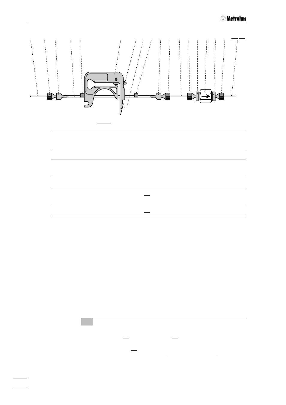
Fig. 6: Installing pump tubings
44
Tubing cartridge
20
20 PEEK compression fitting
(6.2744.010)
55
Contact pressure lever
21
21
Connector (6.2824.110) with filter
77
Snap-action lever
22
22
Housing for 6.2824.100 Filter unit
PEEK
16
16
PTFE tubing (6.1803.020)
23
23
Connector
17
17
Coupling (6.2744.030)
90
90
Suppressor inlet capillary for
H
2
SO
4
18
18
Pump tubing (6.1826.050)
93
93
Suppressor inlet capillary for H
2
O
19
19
Stopper (white-yellow)
•
Press contact pressure lever 55 on both tubing cartridges
down as far as it will go.
•
Insert a length of pump tubing 18
18 (6.1826.050) into each of
the tubing cartridges as shown in Fig. 6. The white-yellow
stopper 19
19 must click into the corresponding holder on the
left-hand side of the tubing cartridge.
•
Place the tubing cartridges on mounting pin 99 and press
down on the right-hand side until snap-action lever 77 clicks
into position on holding clamp 66. Take care that no kinks are
formed in the pump tubing.
8 Suppressor connection 2: H
2
SO
4
•
Loosen rotary nipple screwed onto the interior side of con-
nection 27
27. Pull inlet capillary 90
90 marked with "H
2
SO
4
" (see
Fig. 17 of 732/733 Manual) by hand out of the opening of
connection 27
27 as far as required. Retighten nipple on the in-
terior side of connection 27
27 to fix inlet capillary 90
90.