The gimbal description, Gimbal description, Tips – DJI Z15-5D User Manual
Page 7
©2013
DJI Innovations. All Rights Reserved.
7
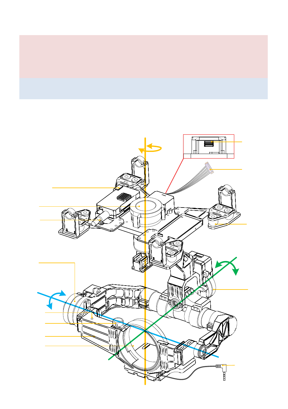
The Gimbal Description
Notes:
Make sure nothing blocks the servo driver module rotation to avoid motor damage.
Clear the obstacles at once if the rotating gimbal is blocked.
No mechanical and electrical adjustment or change is permitted.
Tips:
Each servo driver module has two G8 ports, which are used to transmit servo and video signals.
Z15-5D MARK II
Servo Driver
Module 1
Servo Driver
Module 1
360° continuous rotation
360° continuous rotation
±25°
±25°
-120°~+15°
-120°~+15°
Servo Driver
Module 2
Servo Driver
Module 2
Servo Driver
Module 3
Servo Driver
Module 3
8-pin Cable
Connect the
GCU and Gimbal
8-pin Cable
Connect the
GCU and Gimbal
Video Transmission
Cable
To the A/V OUT port
of 5D Mark II
Video Transmission
Cable
To the A/V OUT port
of 5D Mark II
Lens Mount
Position
Lens Mount
Position
Damping Unit
Damping Unit
The Mounting Board
for Receiver
The Mounting Board
for Receiver
IMU Module
IMU Module
Lens Retaining
Ring' s Screw
Lens Retaining
Ring' s Screw
Cable Clamp
Cable Clamp
ROLL
ROLL
TILT
TILT
PAN
PAN
Gimbal status
Indicator
Gimbal status
Indicator
8-pin Port
To the G8 port
of GCU
8-pin Port
To the G8 port
of GCU