The gcu connection, Gcu connection, Battery – DJI Z15-5D User Manual
Page 15: 4s~12s), A2/wkm/ ace one/ ace waypoint
©2013
DJI Innovations. All Rights Reserved.
15
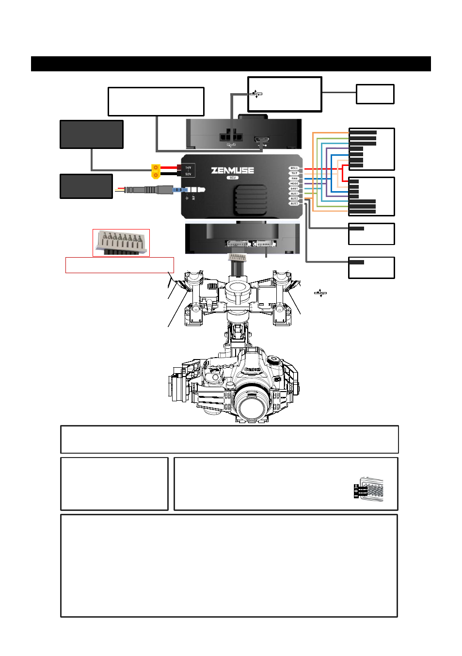
The GCU Connection
The GCU Connection
Gimbal Controller (GCU)
Transmitter and Receiver
·
Above are example connections, which require two transmitters and two receivers. One transmitter and receiver are used
for gimbal control and the other are used for aircraft control. Users can also use a transmitter and a receiver to control
both the gimbal and aircraft.
·
Configure the Aileron, Elevator, Rudder channels on the transmitter for gimbal control. Command stick stands for the
gimbal rotation velocity,the center position is for 0 and the endpoint for maximum velocity (both clockwise and counter
clockwise directions). (End Point is 100%)
·
Choose one 3-position switch/channel as the Z15 working modes switch.(MODE)
·
Choose one 2- position switch/channel as the camera shutter control switch(SHUT), one for the camera lens orientation
switch in Reset Mode (AUX2).
·
Please refer to the A2/ WKM/ACE ONE/ACE Waypoint User Manual for aircraft control setting.
·
Connect the receiver to GCU correctly.
Battery
·
Make sure the battery voltage is in the required range of both the aircraft and the gimbal if you use only one battery for
power supply.
Battery
(4S~12S)
·
Make sure the ports are accessible when installing the GUC so as to facilitate
wiring and software configuration.
·
In 3-pin ports, pins near the nicks are the signal pins.
·
DO NOT cover the heat sinks, keep them unobstructed.
·
The GCU module is NOT water-proof or oil-proof.
Wireless Video
Transition Module
Air End
A2/WKM/ACE ONE/ACE Waypoint
Refer to the A2/ WKM/ACE ONE/
ACE Waypoint User Manual for more
connection and configuration details.
A2/WKM/
ACE ONE/
ACE Waypoint
For WKM/ACE ONE/ACE
Waypoint, connect to any spare
CAN-Bus port of the flight
control system via a CAN-Bus
cable.
For A2, connect to the port
labeled CAN1, located on the
A2 Controller unit or the CAN
port located on any modules
which are already connected to
the CAN1 port via a CAN-Bus
cable.
RC Receiver
(Aircraft control)
Or
RC Receiver
(Futaba
/ Hitec)
7
1
2
4
RC Receiver
(JR)
AUX2
RUDD
ELEV
AILE
2-Position Switch
2-Position Switch
2-Position Switch
2-Position Switch
8-Channel
8-Channel
Micro-USB Port
PC connection for configuration and
firmware upgrades via a Micro-USB
cable.
Heat
Sinks
Ensure the side with copper contacts is
facing upward towards the heat sinks.
2-Position Switch
2-Position Switch
S-Bus Receiver
(Futaba)
S-Bus
Or
PPM Receiver
PPM
Or
G8
CAN-Bus port of GCU
Reserved &
Disconnected
5D