ClearCube M1020W-Series Engineering Workstation User Manual
Page 10
Page 10 of 14
P/N G0200157 Rev E, 1.4.12.11.2014
ClearCube Technology, Inc.
3700 W Parmer Lane
Austin, TX 78727
(512) 652-3500
www.clearcube.com
Setting up an M1020W-Series Engineering Workstation
M1022W
cabling
This section shows how to connect cables. Numbers in parentheses correspond to labels shown in
“
M1022W rear ports and connectors
” to ease identification.
Step
Action
1
Install the included mounting rails to the server chassis and then install the chassis
in a rack.
2
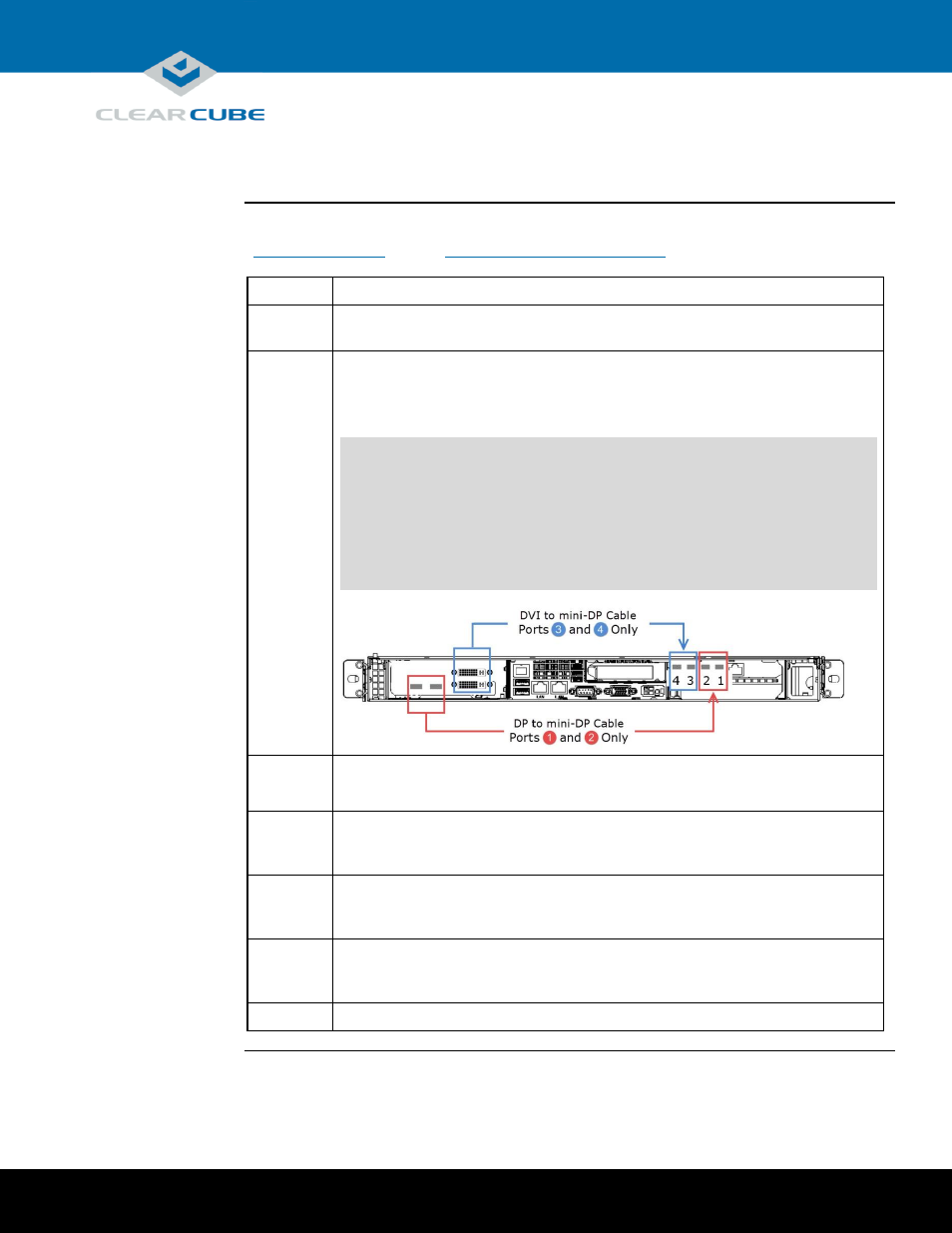
From the rear of the chassis, use the included video cables to route video from the
PCoIP host card to the GPU. Use the DP to mini-DP cables, DVI to
mini-DP cables, or both, depending on the workstation’s dual- or quad-video
configuration.
NOTE: Host card mini-DP ports are ordered from 1 (rightmost) to 4 (leftmost). Be
sure to use ports as shown below when connecting cables from the host card
to the GPU (using different ports can cause display issues).
Connect DP to mini-DP cables from the GPU to mini-DP ports 1 and 2
on the host card (see picture below).
Connect DVI to mini-DP cables from the GPU to mini-DP ports 3 and 4
on the host card (see picture below).
3
Connect an Ethernet cable to the dedicated PCoIP LAN port (20) and connect the
other end to a network router or switch.
4
Optionally, connect one or more Ethernet cables to the LAN ports (14) and (15)
on the rear of the chassis and connect the other end of the cable(s) to a network
router or switch.
5
Optionally, connect one or more Ethernet cables to the Dedicated IPMI port (11)
on the rear of the chassis and connect the other end of the cable to a network router
or switch.
6
From the rear of the chassis, connect the included power cable to the power
connector (21) on the rear of the server, and connect the power cable to a
power outlet.
7
From the front of the chassis, press the power button (7) to power on the server.
Continued on next page
GPU
Host Card