Installation, Chapter 3 – Bird Technologies 6151A User Manual
Page 15
Chapter 3
Installation
This chapter provides information for preparing the 6151A for use.
Location
Free air circulation around the wattmeter is essential. Position the Model 6151A
with clearance around it and do not place it near heated surfaces. The wattmeter
should have at least a 4 inch clearance on all sides. Keep the space above the Model
6151A unobstructed to provide adequate natural air convection for good heat transfer.
Use the wattmeter in a horizontal position only.
CAUTION
Do not drop the instrument or Plug-In Elements as damage to the meter could result or
impair the accuracy of the elements.
Mounting
The Model 6151A Termaline Wattmeter is essentially a portable test instrument. It
should be placed as close as possible to the equipment of which the RF power is
being measured.
The wattmeter may be fastened to a work or test surface by removing the four rubber
bumpers from the bottom of the radiator. These bumpers are fastened to the radiator
brace by 8-32 studs which are molded permanently into the rubber feet. The bumpers
unscrew easily by hand. The holes are threaded for 8-32 screws. Fasteners must be
placed up through the work surface and into the radiator. These holes are on a 3
by 7 inch rectangle, (76 x 178 mm).
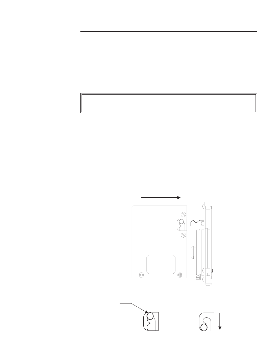
Latch Mechanism
The meter housing is retained on the radiator by the bowed-spring action of the
latch spring, which is a rod of heavy wire. While following these instructions, refer
to figure 4.
Unlatched
Latched
Button
Figure 4
Latch Operation
5