Introduction, Chapter 1 – Bird Technologies 6151A User Manual
Page 11
Chapter 1
Introduction
Purpose and
Function
The Bird Model 6151A Termaline RF Wattmeter is designed to measure RF power
under non-radiating conditions. The Wattmeter is coupled to an accurate 50 ohm
coaxial load resistor which becomes the transmitter load element, providing a
practically reflectionless coaxial line termination up to 2.3 GHz.
Power input to the load resistor is sampled by a coupler-detector type voltmeter
indicating directly in watts.
The Model 6151A is intended for general field and laboratory service use on CW,
AM and FM modulation envelopes, but not on pulsed modes.
Description
The Model 6151A Termaline Wattmeter consists of a coaxial load resistor, detector
circuit, dc cable, panel meter and its housing.
The load portion is comprised of an RF coaxial load resistor assembly encased in a
finned radiator. The detector circuit is in the Plug-in Element inserted in a short
length of 50 ohm coaxial line mounted on the front of the load portion. A 2-3/4 foot
(83.8 cm) coaxial cable (RG-58/U) connects the detector circuit to the meter which is
sealed and shock mounted in its housing.
The detector circuit in the Plug-in Element samples the RF energy travelling toward
the load, converts it to a small dc voltage for readout on the meter. The meter scale
is designed to indicate power directly in watts.
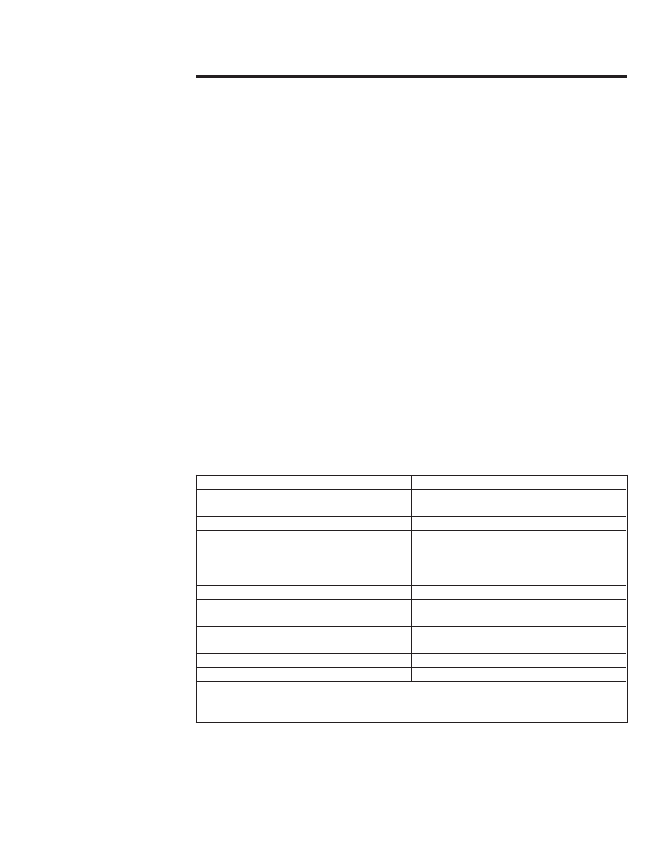
Specifications
Power Rating
100 W continuous
Power Ranges
25/50/100 Determined by plug-in
elements*
Input Impedance
50 ohms nominal
Frequency Range
2 to 2300 MHz Determined by plug-in
elements*
VSWR
1.1 to 1.0 max. dc to 1 GHz
1.25 to 1.0 max. 1 to 2.3 GHz
Accuracy
± 5% of full scale to 2.3 GHz
Input Connector
Bird quick change “QC” type Female N
normally supplied.
Dimensions
12-27/32" L x 3-15/16" W x 6-11/32"H
(326 x 100 x 161 mm)
Weight, Nominal
8 lb (3.6 kg)
Finish
Grey Powder Coat
*Refer to the Bird Electronic Corporation Catalog.
Any Element, up to 100 watts, may be selected from Tables I, II or III of the Cata-
log.
1