Bird Technologies 4331 User Manual
Page 22
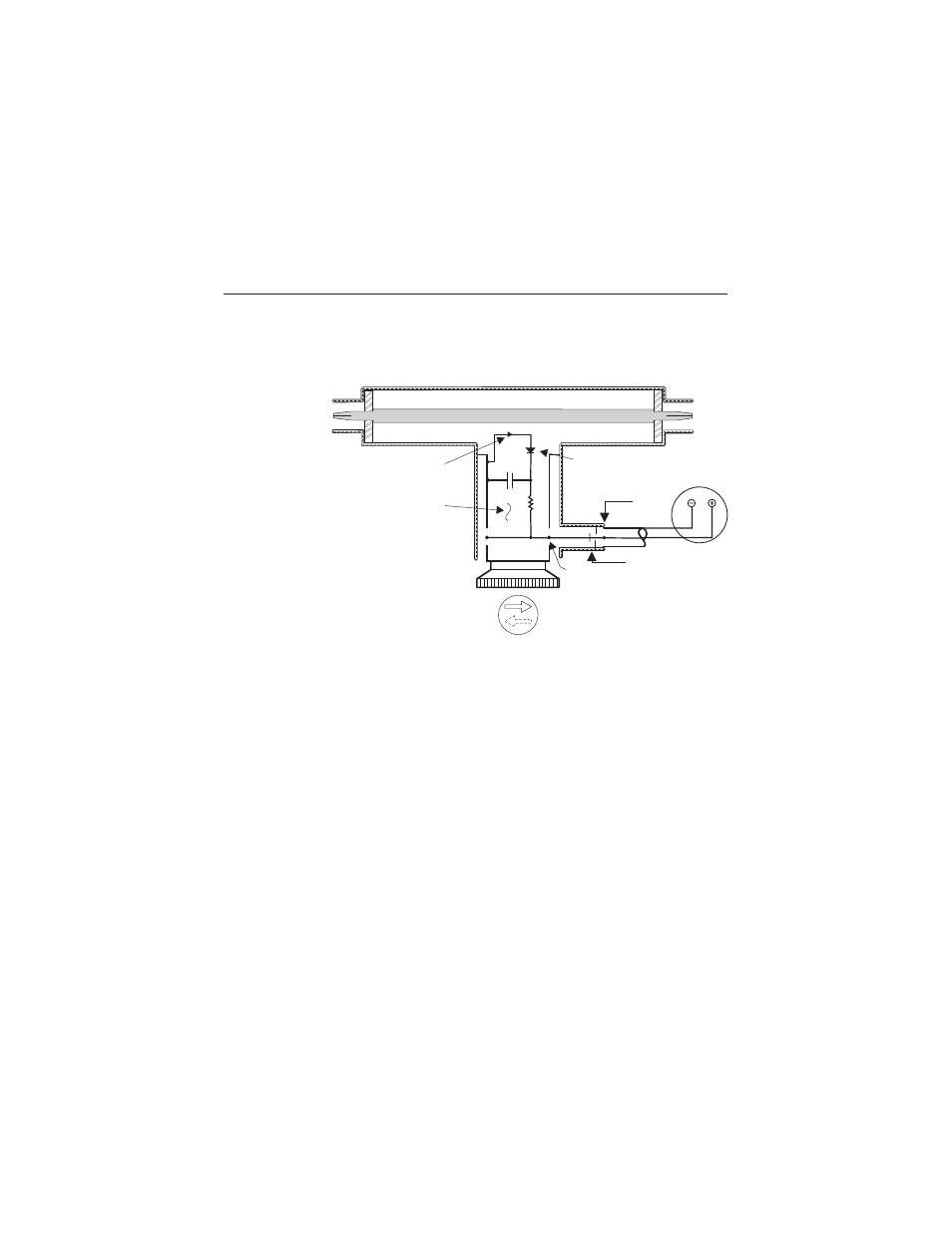
components of the Model 43 are illustrated in the Schematic diagram, figure
3.
Energy will be produced in the coupling circuit of the element by both mutual
inductance and capacitance from the travelling RF waves in the line section.
The inductive currents will flow according to the direction of the travelling
waves producing them. The capacitive portion of these currents is inde-
pendent of the direction of the travelling waves. Therefore, assuming that
the Plug-In Element remains stationary, it is apparent that the coupling
currents produced from the waves of one direction will add in phase, while
those produced from the waves of the opposite direction will subtract in
phase. The additive or arrow direction is assigned to the forward wave.
The electrical values of the element circuits are carefully balanced and so
designed that the inductive current produced from the reverse wave will
cancel its portion of the capacitive current almost completely. The result is
a directivity always higher than 25 dB, which means that the element is
highly insensitive (nulled) to the reverse direction wave. By being highly
directional, the element is sensitive at either one of its settings, but to only
one of the two travelling waves which produce standing waves by interfer-
RF Coaxial Line
XMTR
or
LOAD
LOAD
or
XMTR
Directional Coupling
Detector Element
Diode
Meter
DC Contact
Bypass
DC
Connector
Figure 3
Element
Schematic
Diagram
Bird Model 43 Wattmeter
8