Bird Technologies 8833-300 User Manual
Page 7
free standing or can be attached to a bench, etc.,
Refer to Figure-1, Outline Drawing, for location of the
two mounting brackets and four mounting holes.
Attach the load using four suitable fasteners.
2.2
Orientation
This equipment is designed for operation in an up-
right position only, as shown in Figure-1, Outline
Drawing. Do not attempt to operate in any other
position.
2.3
Vent
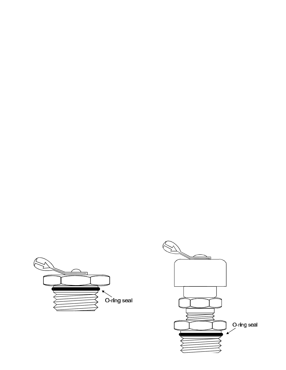
The coolant filler inlet is capped with a shipping plug,
Figure-2, during transport from the factory. The ship-
ping plug must be removed and replaced with the
vent plug, Figure-3, before operation. The vent plug
must also remain installed during cooling.
2.4
Installing Vent Plug
Warning
Failure to properly vent the radiator during operation
and cooling can result in equipment damage and
personal injury.
Remove the shipping plug using a 3/4" flat wrench.
Ensure the o-ring seal stays in place on the shipping
plug.
Ensure the o-ring seal is in place on the vent plug.
Install vent plug.
2.5
Thermoswitch
A
thermoswitch assembly, P/N 2450-056, is an avail-
able option. When installed in the radiator, it will
prevent damage from accidental transmitter power
overload or equipment malfunction. Being normally
closed, the thermoswitch opens at a maximum safe
temperature. Connected in series with the transmitter
interlock, it cuts off transmitter power if load tempera-
ture exceeds this value. The assembly consists of
the thermoswitch body, P/N 2450-040, with coupling
jack, P/N 2450-018, attached.
Thermoswitch Installation
Place the unit on its back, with the connector end
up. This position prevents coolant spillage.
Use a 9/16 allen wrench to remove the socket plug
on the front face of the radiator.
Replace the plug with the thermoswitch. Use an
acceptable pipe sealing compound sparingly, on the
external threads only, of the thermoswitch. Do not
contaminate coolant with pipe sealing compound.
Observe closely for coolant leaks upon completion.
Connecting the Thermoswitch, see Figure-4
Unscrew the knurled ring-nut [A] at the lower end of
the coupling jack assembly. Pull it off the ther-
moswitch jack [B].
Unscrew the small knurled cover fitting [C] from the
base plug [D] of the connector to release the base.
Thread the interlock wires through the clamp [E] (with
washers [F] inside) and with its threaded fitting in
p
l
a
Figure - 2
Shipping Plug
Figure - 3
Vent Plug
RF Load Resistor Model 8833-300
Page 7