Bird Technologies 8833-300 User Manual
Page 11
band for coolant leakage. If leakage is observed:
Tighten the clamping screw if required. If the coolant
continues to leak, proceed to step (b).
Replace the resistor housing o-ring seal. Follow in-
structions for removing and installing the load resistor
in paragraphs 5.3 through 5.4.
5.6
Checking Coolant Level
The dielectric coolant level should remain constant
under normal operating conditions, but should be
checked periodically.
Place the unit on its back, with the connector end
up.
Remove the load resistor following instructions start-
ing in paragraph 5.3.
At room temperature the coolant level should be
4-3/4 inches (121 mm) below the top surface of the
load resistor assembly mounting ring.
Note: The unit is filled at the factory— to the level described in step (c)—with 2.9 gallons (11 liters)
of specially selected dielectric fluid. Do not use any other coolant.
Add amount of coolant, p/n 5-030, required to bring
coolant up to the level described in step (c).
Install the load resistor following instructions starting
in paragraph 5.4.
5.7
Pressure Vent
When the coolant oil is heated, thermal expansion
will cause an increase in internal pressure. The vent
plug—when properly installed in the coolant inlet of
the radiator tank—provides a vent to relieve this
pressure and prevents dirt and other contaminants
from entering the radiator.
Ensure the vent plug is in place and free from
obstruction during operation and cooling.
5.8
RF Input Connector
The input connector on the Model 8833-300 is a Bird
Quick-Change or “QC” connector. As the name im-
plies, changing the connectors is easy and quick.
Connectors can be changed without disturbing the
coolant seal or interfering with coaxial continuity of
the load resistor input.
Replacing the RF Input Connector
Remove the four 8-32 x 5/16 inch round head ma-
chine screws from the corners of the RF connector
flange.
Pull the connector straight out.
Reverse the above procedure to install new connec-
tor, making certain that the projecting center contact
pin of the “QC” connector is carefully engaged and
properly aligned with the mating socket of the load
resistor.
The “QC” connector may be replaced with other
standard AN type connectors if obtained from Bird
Electronic Corporation. At the full power and fre-
quency capability of this model, only type LC or LT
(Female or Male) or 7/8 inch EIA (air line) connectors
will be adequate. For any other connector type, input
power must be limited to the specifications of the
selected type.
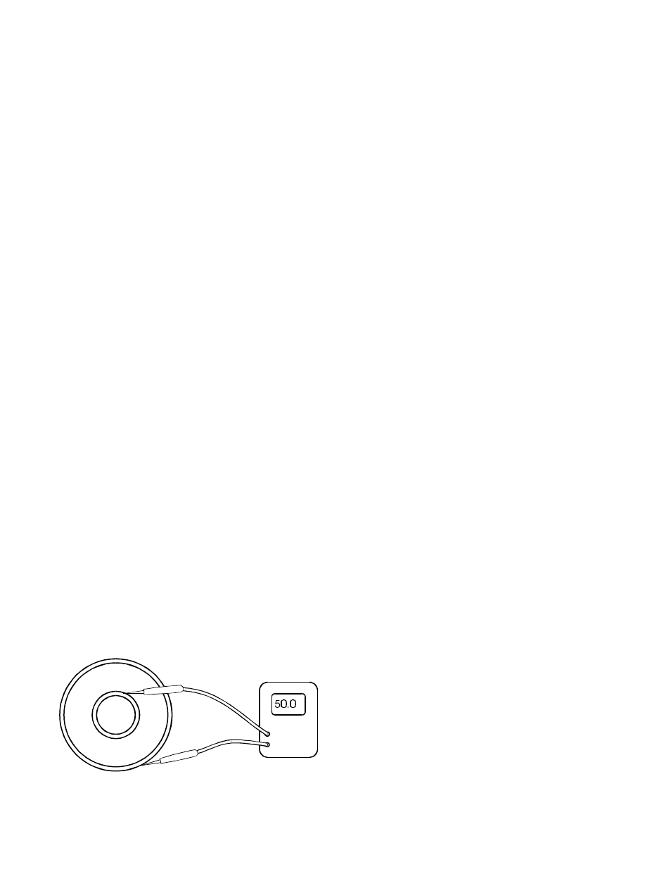
Figure - 6
Checking DC Resistance
RF Load Resistor Model 8833-300
Page 11