Bird Technologies 8251D208 User Manual
Page 26
These tests are by no means a necessity to the operation of
the load but merely guidelines for the users information.
Disassembly
There are no special techniques required for the repair or
replacement of components in this Termaline Load Resistor.
Tools
Required
s
screwdriver
s
small wrench
s
adjustable wrench (for the connector bolts)
RF Connector
The Model 8251D208 has a 1-5/8 inch EIA flanged connector
and must be returned to the factory for connector replace-
ment.
Rear Seal and
Coolant
Before any disassembly of the rear of the load, if the coolant
has not already been drained from the tank, stand the ra-
diator on end with the connector pointed down.
1. Unscrew the four 10-32 screws at the corners of
the guard cover.
2. Unscrew the tube nut from the tank nozzle, us-
ing a small wrench if necessary, and pull the
nozzle free.
3. Loosen the clamp screw with a screwdriver from
the bottom of the clamping band, same type as at
the front, and remove the clamping band.
4. Remove the rear cover which includes the at-
tached escape tube with captive nut, P/N 2430-
088, and the diaphragm seal, P/N 2430-089.
14
Bird Model 8251D208
Termaline Coaxial Load Resistor
50.0
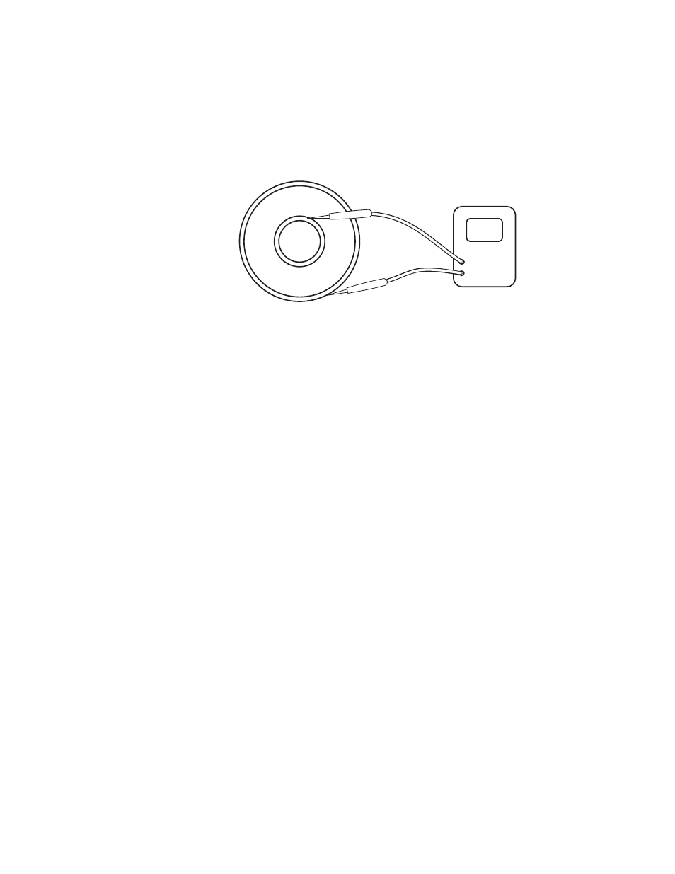
Figure 4
Measuring DC
Resistance