Bird Technologies 8251D208 User Manual
Page 20
Connecting to
the
Transmitter
Connect the load to the transmitting equipment under test
with 50 ohm coaxial cable (RG-8A/U, RG-9/U, RG-213/U or
equivalent). After the transmitter has been connected to the
load, proceed according to the transmitter manufacturer’s
instructions. When reconnecting the antenna, it may be nec-
essary to slightly readjust the transmitter due to possible
differences in VSWR between the load and the antenna sys-
tem.
The 1-5/8 inch EIA flange connector is fastened to the trans-
mission line by four 5/16-18 x 1-1/2 bolt sets. The center con-
ductors must be joined with a bullet for 50 ohm 1-5/8 inch
coaxial lines. Bird P/N 4712-020 Bullet Kit includes the bolt
sets, O-Ring, and center conductor bullet.
+
Note: Avoid the use of adapters and elbows
whenever possible.
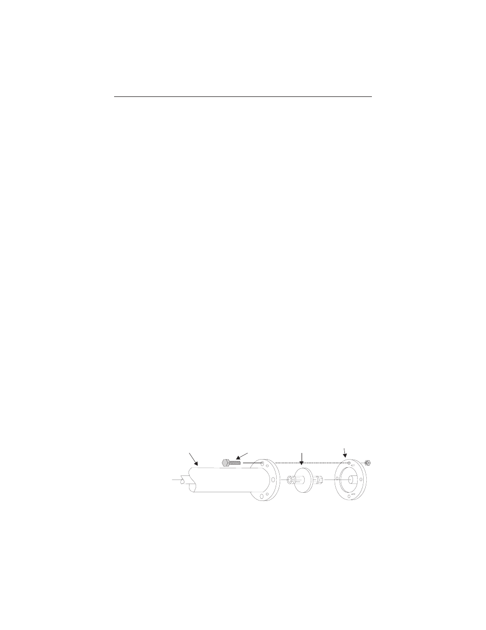
Refer to figure 3 while following the instructions below.
1. Seat the bullet so that half of the thickness of
the insulator is nested in the counterbore of each
connector flange.
2. Place the load resistor so that it will be aligned
with the coaxial input line.
3. Push in on the center contact.
4. Tighten the flange nuts evenly all around (finger
tight).
5. Tighten the nuts evenly with wrenches.
8
Bird Model 8251D208
Termaline Coaxial Load Resistor
RF Coaxial Line
Bolt
Bullet
Flange
Figure 3
Connection to
Transmitting
Equipment