Bird Technologies 6150-PAGE-Manual User Manual
Page 8
TXRX Systems Inc. Manual 7-9419-1 05/19/06 Page 5
lifted straight out the overhang could possibly
damage the interface circuit board.
C) With the display user interface assembly stand-
ing up straight gently move it upwards while lift-
ing it out an inch or two. This should allow the
overhang to clear the interface circuit board
without damage.
D) Remove the ribbon cable that connects the dis-
play user interface assembly to the card cage.
Refer to Figure 6.
E) With the display user interface assembly tem-
porarily moved out of the way, route the DC
cable from the dialer through the inside of the
card cage along the path shown by the dotted
line in figure 5.
F) Replace the display user interface assembly by
following steps D through A in reverse order.
9) Connect the four conductor cable from the
dialer to the alarm terminal screws inside of the
booster cabinet as shown in Figure 7.
10) Connect a telephone line to the “TEL IN” con-
nector on the top of the dialer unit. See figure
4.
11) This completes the installation of the automatic
voice/pager dialer. The unit must be pro-
grammed for proper operation. Refer to the
OEM operating manual for programming spe-
cifics.
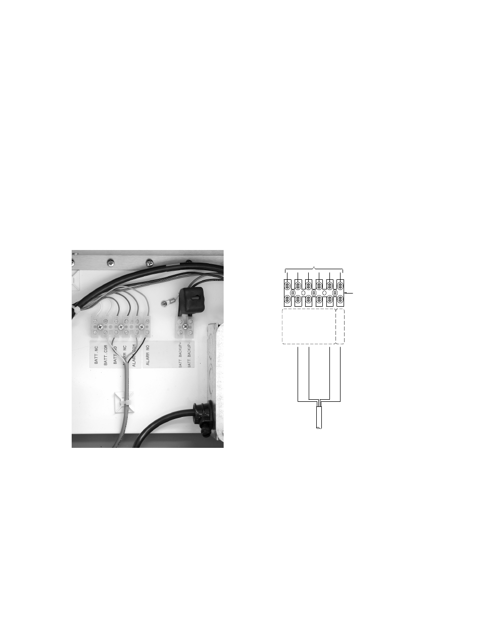
Figure 7: Connecting the 4 conductor cable to the SB II alarm terminal screws.
Batt. COM
Batt. NC
Batt. NO
Alarm NC
Alarm NO
Alarm COM
6-POSITION
TERMINAL
EXISTING WIRES
IN SIGNAL
4-CONDUCTOR
FROM AUTO DIALER
Red
to Batt NO
Wh
ite
to Batt COM
B
lack
to
Alarm NO
Green
to
Alarm COM