Bird Technologies 6150-PAGE-Manual User Manual
Page 5
TXRX Systems Inc. Manual 7-9419-1 05/19/06 Page 2
C
L
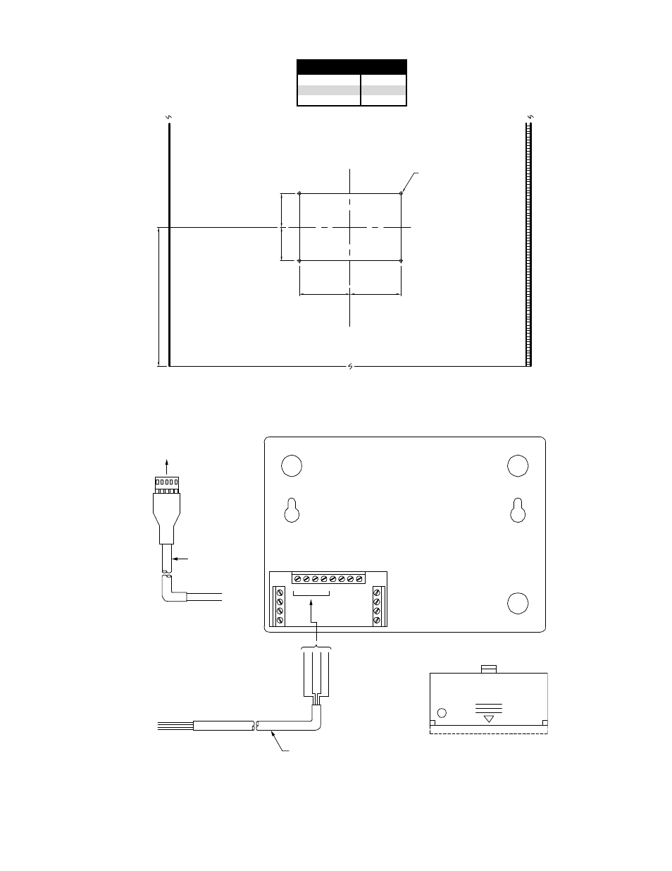
.136 DIA. THRU
4 - PLACES
REQUIRED DRILLING LAYOUT FOR
MOUNTING AUTO DIALER TO SIGNAL BOOSTER
ENCLOSURE DOOR (INSIDE)
BOTTOM OF DOOR
-A- DIM (See Char
t)
1.500
1.500
2.250
2.250
700 MHz
800 MHz
900 MHz
8.75"
8.75"
8.75"
SBII MODEL
-A- DIM
Figure 2: Template for installing the mounting plate to the cabinet door.
1
+
-
-
+
12VDC
AUX
OUT
1 C
C
2
4 C
C
3
IN
OUT
Red to +
Black to -
Red
to
1
White
to
C
Black
to
2
Green
to
C
Back View of Auto Dialer Without Mounting Assembly
Board Assembly in
Card Cage Sub-Assy
DC Cable Assy
4-Conductor Cable
Remove lower pre-etched
tab of back cover plate
Wires to
12VDC
Wires to
Channels 1 & 2
Channels
Tel
Figure 3: Connecting cables to the rear of the dialer unit.
See also other documents in the category Bird Technologies Accessories communication:
- SK-4000-TC-Manual (56 pages)
- SK-4000-TC-Datasheet (2 pages)
- SH-36S-Manual (206 pages)
- SH-36S-Datasheet (4 pages)
- SH-36S-PC-Manual (130 pages)
- SH-36S-PC-Datasheet (2 pages)
- SH-36S-PC-Quick Start (2 pages)
- SH-36S-RM-Datasheet (2 pages)
- SA-3600XT-Manual (112 pages)
- SA-3600XT-Datasheet (2 pages)
- AT-500-Manual (73 pages)
- AT-500-Datasheet (2 pages)
- AT-800-Manual (74 pages)
- 89-83F-02-03-Manual (2 pages)
- 89-83F-02-03-Datasheet (1 page)
- 8251 Series-Datasheet (1 page)
- 8251 Series-Manual (30 pages)
- DA10 VHF Series-Datasheet (2 pages)
- DA10 VHF Series-Manual (47 pages)
- 8865SC13-Datasheet (2 pages)
- 8865SC13-Manual (28 pages)
- 8890-300SC13-Manual (28 pages)
- 8921SC13-Manual (28 pages)
- 8931-115SC13-Manual (34 pages)
- BDS-Datasheet (2 pages)
- BDS-Manual (98 pages)
- SCC7 Series-Datasheet (2 pages)
- SCC7 Series-Manual (45 pages)
- MSCC7 Series-Datasheet (2 pages)
- MSCC7 Series-Manual (35 pages)
- SCC8 Series-Datasheet (2 pages)
- SCC8 Series-Manual (47 pages)
- 4020 Series-Datasheet (1 page)
- 4020 Series-Manual (4 pages)
- 4027A Series-Datasheet (2 pages)
- 4027A Series-Manual (6 pages)
- 4027F Series-Datasheet (2 pages)
- 4027F Series-Manual (6 pages)
- 4028 Series-Datasheet (2 pages)
- 4028 Series-Manual (6 pages)
- 7022-Datasheet (4 pages)
- 7022-Manual (27 pages)
- ACM Series-Datasheet (2 pages)
- ACM Series-Manual (40 pages)
- BPME Series-Datasheet (4 pages)