Figure 5: connecting the dc cable to the card cage – Bird Technologies 6150-PAGE-Manual User Manual
Page 6
TXRX Systems Inc. Manual 7-9419-1 05/19/06 Page 3
rear of the dialer to the alarm terminal screws
and the card cage within the booster cabinet.
2) Drill out four 0.136 inch diameter holes at the
positions you marked on the cabinet door.
3) Attach the mounting plate to the inside of the
door with four Phillips screws (4-40 x 3/16”).
4) Remove the cover plate from the rear of the
dialer unit to expose the terminal screws. Con-
nect the wires from the 4 conductor cable to the
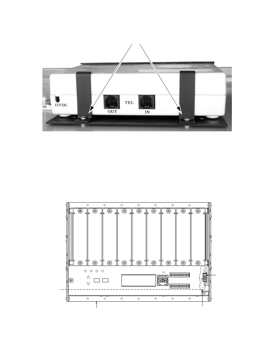
Figure 4: Hold down brackets for the dialer unit.
Attach brackets with 4-40 x 3/16”
phillips head screws
R11
R12
Enter
24v
12v
UL PA
Cancel
DL PA
DOWNLINK OLC
UPLINK OLC
SYSTEMS
INC.
DC CABLE ASS'Y.
FROM AUTO DIALER
CARD CAGE SUB-ASS'Y.
IN SIGNAL BOOSTER
PATH
FOR DC
CABLE
Pin #1
Black Wire
Figure 5: Connecting the DC cable to the card cage.
- SK-4000-TC-Manual (56 pages)
- SK-4000-TC-Datasheet (2 pages)
- SH-36S-Manual (206 pages)
- SH-36S-Datasheet (4 pages)
- SH-36S-PC-Manual (130 pages)
- SH-36S-PC-Datasheet (2 pages)
- SH-36S-PC-Quick Start (2 pages)
- SH-36S-RM-Datasheet (2 pages)
- SA-3600XT-Manual (112 pages)
- SA-3600XT-Datasheet (2 pages)
- AT-500-Manual (73 pages)
- AT-500-Datasheet (2 pages)
- AT-800-Manual (74 pages)
- 89-83F-02-03-Manual (2 pages)
- 89-83F-02-03-Datasheet (1 page)
- 8251 Series-Datasheet (1 page)
- 8251 Series-Manual (30 pages)
- DA10 VHF Series-Datasheet (2 pages)
- DA10 VHF Series-Manual (47 pages)
- 8865SC13-Datasheet (2 pages)
- 8865SC13-Manual (28 pages)
- 8890-300SC13-Manual (28 pages)
- 8921SC13-Manual (28 pages)
- 8931-115SC13-Manual (34 pages)
- BDS-Datasheet (2 pages)
- BDS-Manual (98 pages)
- SCC7 Series-Datasheet (2 pages)
- SCC7 Series-Manual (45 pages)
- MSCC7 Series-Datasheet (2 pages)
- MSCC7 Series-Manual (35 pages)
- SCC8 Series-Datasheet (2 pages)
- SCC8 Series-Manual (47 pages)
- 4020 Series-Datasheet (1 page)
- 4020 Series-Manual (4 pages)
- 4027A Series-Datasheet (2 pages)
- 4027A Series-Manual (6 pages)
- 4027F Series-Datasheet (2 pages)
- 4027F Series-Manual (6 pages)
- 4028 Series-Datasheet (2 pages)
- 4028 Series-Manual (6 pages)
- 7022-Datasheet (4 pages)
- 7022-Manual (27 pages)
- ACM Series-Datasheet (2 pages)
- ACM Series-Manual (40 pages)
- BPME Series-Datasheet (4 pages)