Bennett Marine Premier Line Systems User Manual
Page 4
Step 3: Drilling the Holes for Actuators
DUAL ACTUATOR SYSTEMS (2 ACTUATORS PER SIDE)
These systems consist of two actuators per trim tab — one with
sensor and one without sensor. The actuator with the red sensor wire
installs on the port side of the boat, and the actuator with the green
sensor wire on the starboard side of the boat.
IMPORTANT: The hole for the sensor wire must be accurate
— match the paper template exactly so that the wire goes
through the transom easily. Be careful not to crush or pinch
the wire while mounting the actuator.
(See Figure 2) For this step, use the two actuators WITHOUT the
sensor wires. You will do this for each side of the boat:
1. Each trim tab is installed as an extension of the hull. To achieve
this, position the upper mount of each actuator with the trim tab on
the same plane as the hull bottom.
2. Support the trim tab assembly from below while positioning against the transom. Attach both actuators without sensors to the trim
tab using the supplied 5/16-18 x 1 1/4" hex head machine screws.
3. Mark the outline of the four mounting holes in the upper mount. Remove the actuators from the trim tab and set aside.
4. Take both actuator paper templates and put them in position — the paper template with sensor hole should be inboard, and the
template without sensor hole should be outboard. Align the templates and tape to the transom. The templates should be used to mark
and drill the sensor holes and pipe nipple holes. Drilling a small pilot hole first helps locate an accurate center for each hole. Based on
the template, for the actuators with a sensor, drill a 19mm (3/4") hole in the transom for the sensor wire. Drill the marked
8mm (5/16") mounting holes for each actuator. And drill the marked 12mm (1/2") holes for the pipe nipples.
5. Once all the holes are drilled, mount the actuators to the trim plane using the supplied machine screws. DO NOT TIGHTEN.
Note: Actuators WITH sensors should
be mounted inboard. Actuators
WITHOUT sensors should be mounted
outboard.
4
Figure 2
Use Individual Templates to
Drill the Sensor Holes and
Pipe Nipple Holes
Template
Without
Sensor
Use Both Actuators
WITHOUT
Sensors to
Position
the Upper
Mounts and Drill the
Four Mounting Holes
For Each Side of the Boat:
Template
With Sensor
(inboard
actuator)
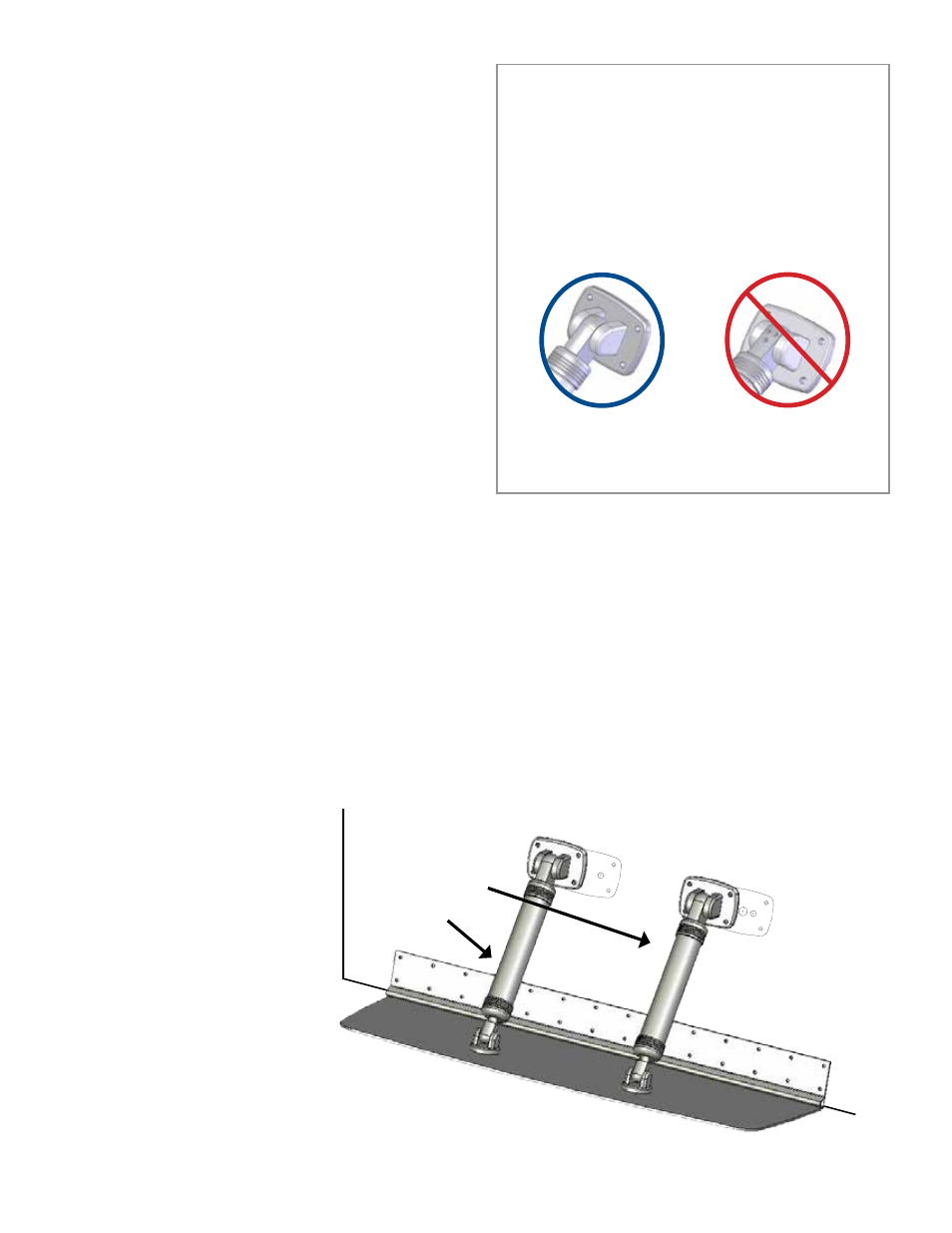
IMPORTANT INSTALLATION NOTICE:
MAKE SURE ACTUATOR UPPER MOUNTS
FACE THE CORRECT WAY
The upper mount is able to pivot through 180 degrees but there
is only one correct way to install it.
An easy guide: Make sure the three black dots in the upper
mount (as shown) are not visible when installed.
CORRECT
No black dots visible
when mounted.
NOT CORRECT
Black dots visible.
PROCEED TO
STEP 4
ON PAGE 6 TO
COMPLETE THE INSTALLATION.