Bennett Marine Auto Tab Control User Manual
Page 3
SECTION 2
BEFORE INSTALLING THE AUTO TAB CONTROL, YOU MUST
CHECK THE TRIM TAB SYSTEM INSTALLATION
The ATC system interfaces with the boat’s trim tab system, and automatically
operates the trim tab Hydraulic Power Unit (HPU). Therefore before you install
and operate the ATC system it is critical you confirm that the HPU wiring and
hydraulic tubing is connected EXACTLY as described in items 1 and 2 below.
1. Hydraulic Tubing:
Tubing from the port actuator must be connected to the fitting marked
•
“P” (front left) on the HPU.
Tubing from the starboard actuator must be connected to the fitting
•
marked “S” (front right) on the HPU.
THE TUBING MUST
NOT
BE REVERSED
2. Helm Control Wiring:
Verify that the four-color wire harness leading to
the back of the trim tab helm control is wired as follows.
For Single Lever and Rocker Switch Controls
Notice the indented letters on the back of the control,
make sure connections are as follows:
• Red wire connects to “R”
• Green wire connects to “G”
• Blue wire connects to “B”
• Yellow wire connects to “Y”
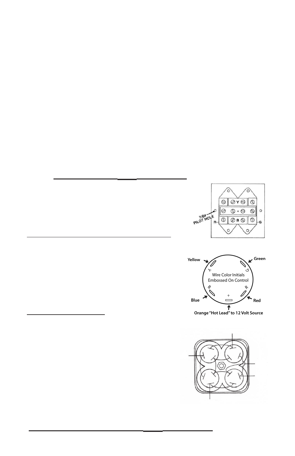
For Racing Type Control
Facing the control, with the word BOW at the top,
turn the control over to the right (or left) and
inspect the control to ensure the wiring is
connected as follows:
• The blue wire is connected to the top two terminals
• The red wire is connected to the two left terminals
• The yellow wire is connected to the two bottom
terminals
• The green wire is connected to the two right
terminals
THE WIRING CONNECTIONS MUST
NOT
BE REVERSED
Single Lever Control
Rocker Switch Control
BLUE
POSITIVE
GREEN
YELLOW
RED
Racing Type Control
3