Bennett Marine Auto Tab Control User Manual
Page 11
Installation Instructions for
Electronic Indicator Control (EIC5000) Systems
IMPORTANT: If you did not purchase the Auto Tab Control set designed for the
Electronic Indicator Control (EIC) you will have to contact Bennett Marine for a
Wire Harness to run from the EIC Module to the ATC Control Unit.
Follow steps 1, 2 and 3 from the Non-Electronic Bennett Trim Tab Control
Systems Instructions.
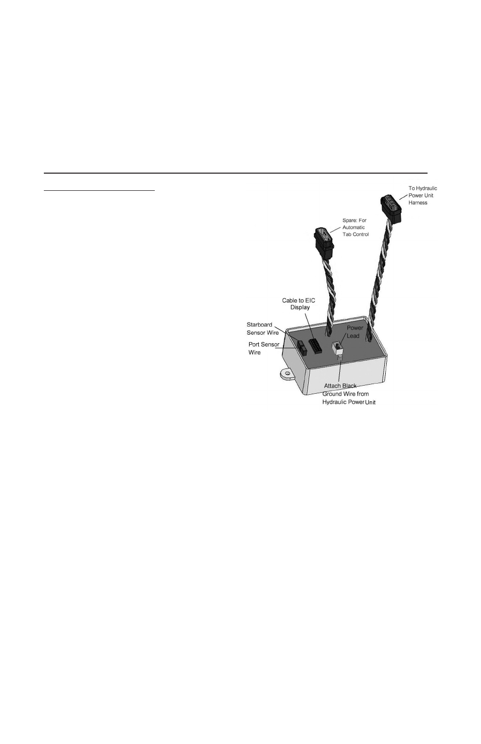
Connecting the ATC Control Unit
to the EIC Relay Module
The EIC Relay Module has a
•
special connector built in for the Auto
Tab Control. It is the shorter of the two
Wire Pigtails coming out of the module.
Connect the 25-foot Wire
•
Harness (WH100025) to this shorter
Wire Pigtail.
Run the Wire Harness to the
•
Control Unit at the helm. Trim the
Wire Harness to the desired length
and strip the wire ends. Strip
approximately 3/16ths of an inch on each wire.
Crimp the butt splices on the Pigtail for Wire Harness (PT109) onto the
•
Wire Harness, matching color to color.
Plug the Pigtail for Wire Harness (PT109) into the Control Unit connection
•
marked “Relay Module.”
System Check
Plug the ATC Power Pigtail connector into the Control Unit marked “Power
•
Connection.”
Turn the boat power back on.
•
Test the trim tabs using the control. Make sure your trim tabs are working
•
correctly. If not, check the connections on the Control Unit, the EIC Control, and
the Relay Module.
The ON/OFF ATC Keypad button will not activate the ATC system until the ini-
•
tial Zero Point is set. If you turn on the ATC at this point, the blue Zero Set LED
light will flash. Refer to section 3, “Using your Auto Tab Control for the first time.”
(Refer to Diagram on Page 13)
11