Bendix Commercial Vehicle Systems VORAD VS-400 INSTALLATION NOTES User Manual
Page 46
General Information
44
Appendix 4B, 4C
Step
Procedure
B
1.
Vehicle Ignition: Key-ON, Engine-OFF.
2 .
Measure for ignition voltage on pins 4 and 5 on the harness connector .
a .
If the voltage is within 0 .6 volts of the battery voltage measured in Step A .
i .
Proceed to Step C .
b .
If voltage is less than 0 .6 volts of the battery voltage measured in Step A or open .
i.
Test Failed. Check component fuse. Troubleshoot power supply to the DIU for open / corroded
connections or shorts to ground and repeat Step .
Step
Procedure
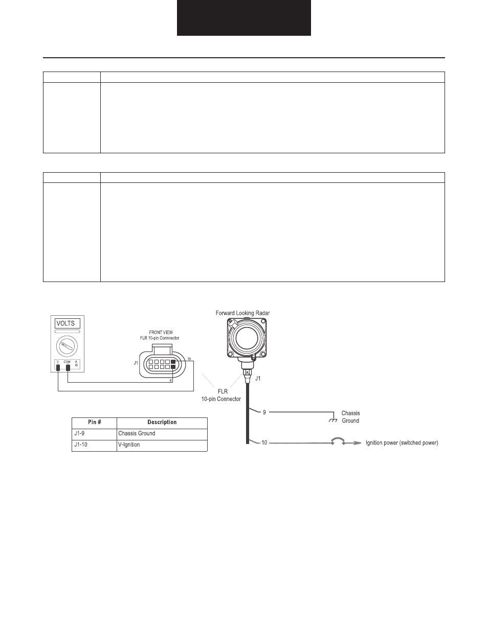
C
1.
Vehicle Ignition: Key-OFF, Engine-OFF.
2 .
Disconnect the 10-way connector from the VS-400 Forward Looking Radar (FLR) .
3 .
Measure for zero voltage on pins 10 and 9 on the harness connector .
a .
If the voltage is 0 .5 volts or less .
i .
Proceed to Step D .
b .
If voltage is greater than 0 .5 volts but less than battery voltage .
i .
Test Failed . Check FLR power supply wiring for sources of stray voltage or shorts to voltage .
c .
If the voltage is within 0 .6 volts of the battery voltage measured in Step A .
i .
Test Failed . The FLR is improperly wired or shorted to a battery power source . Correct the
wiring by connecting the FLR to main ignition power supply bus and repeat Step .