2 adjuster mechanism inspection – Bendix Commercial Vehicle Systems ADB22X-V Air Disc Brakes User Manual
Page 11
11
4.2 ADJUSTER MECHANISM INSPECTION
CAUTION: Follow all safe maintenance practices.
Aside from the normal maintenance schedule, the
adjuster mechanism inspection that follows is also
carried out when the Caliper Movement Test (4.1) fi nds
that the running clearance is too small or too large.
4.2.1 With the spring brake released (or caged), remove
the adjuster cap (37) using the tab, taking care not
to move the shear adapter (61). Note: One of two
styles of adjuster cap (stamped metal or plastic
adjuster cap) may be used.
Adjuster Cap
Location
FIGURE 17 - ADJUSTER CAP LOCATION
61 Adapter
23 Adjuster
37
Cap
Tab
Tab
37
Cap
FIGURE 18 - EXPLODED VIEW
OF ADJUSTER AND ADAPTER
FIGURE 19 - CAP INSTALLED:
TAB LOCATION
For illustration purposes, the exploded view (Figure 18)
shows the adjuster (23) and shear adapter (61) separated.
When using the adjuster mechanism, always have the
shear adapter installed on the adjuster.
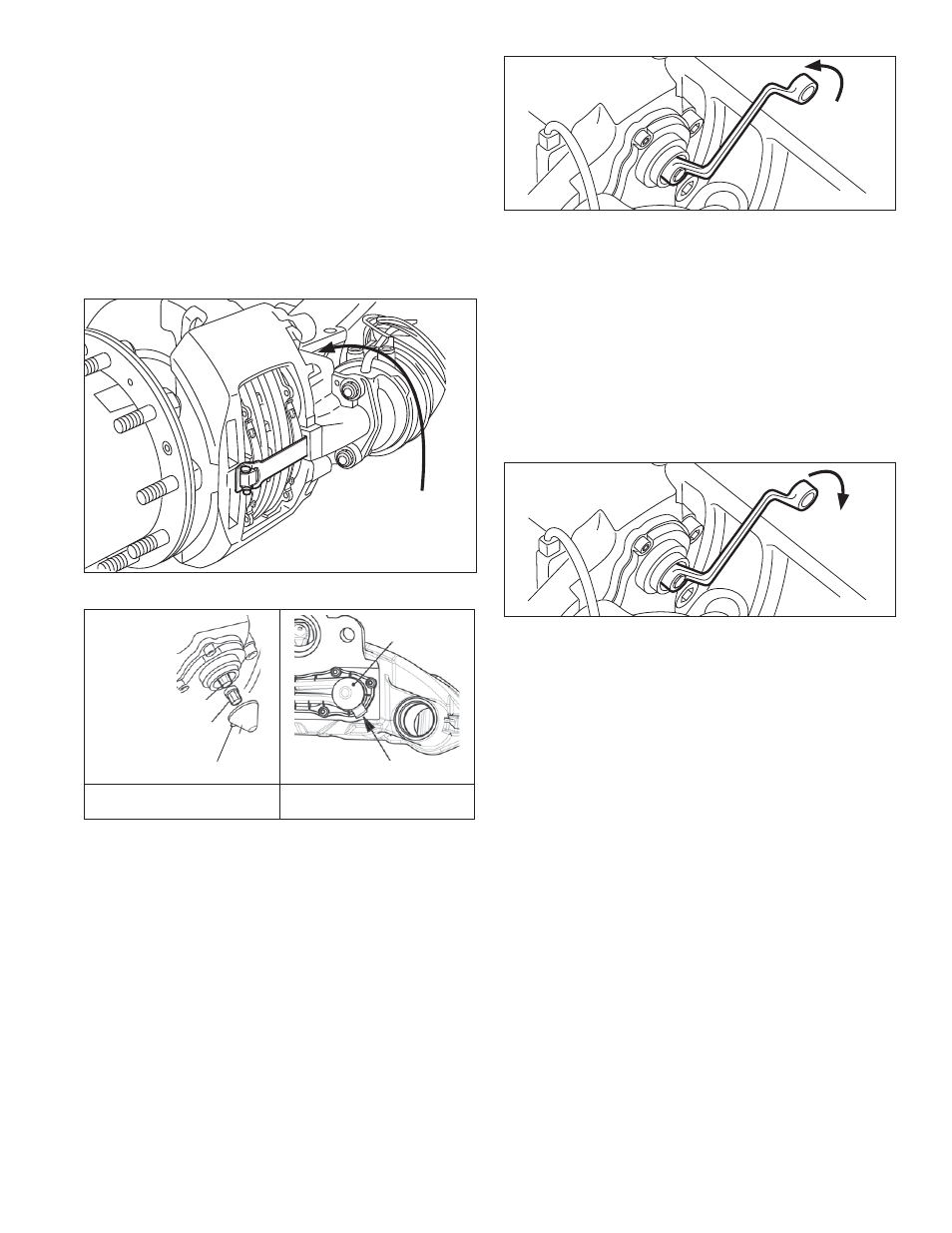
4.2.2 Using a 10 mm. six-point box wrench, turn the Shear
Adapter (61)
counter-clockwise and listen for
the sound of 3 clicks as the mechanism backs-off
(increases) the running clearance. Note: Do not
use an open-ended wrench as this may damage
the adapter. See Figure 20.
CAUTION: Never turn the adjuster (23) without the
shear adapter (61) installed. The shear adapter is a
safety feature and is designed to prevent excessive
torque from being applied to the adjuster. The shear
adapter will fail (by breaking) if too much torque is
applied.
FIGURE 20 - BACKING-OFF (INCREASING) THE RUNNING
CLEARANCE
If the shear adapter fails, you may attempt a second time
with a new (unused) shear adapter.
Note: Always double-check that the spring brake is released
(where applicable) if a shear adapter fails; if this step was
missed, the shear adapter will break off, and it may appear
that the caliper is seized.
In cases where a second failure of the shear adapter
confi rms that the adjustment mechanism is seized, the
caliper must be replaced.
FIGURE 21 - APPLYING MODERATE APPLICATIONS OF THE
BRAKES: THE WRENCH MOVES CLOCKWISE AS THE RUNNING
CLEARANCE IS DIMINISHED
4.2.3 Where the adjuster mechanism is able to be backed-
off normally, position a box-end wrench on the shear
adapter so that it can turn clockwise freely without
coming into contact with parts of the vehicle (See
Figure 21). Make fi ve to ten moderate applications
of the brakes [at about 30 psi (2 Bar)], and observe
that the box-end wrench or socket should turn
clockwise in small increments.
NOTE: As the number of applications increases,
the turning movement will decrease (as the brake
reaches its normal calibration point).
If the box-end wrench does not: (a) turn at all; (b) turns only
with the fi rst application; or (c) turns forward and backward
with every application, the automatic adjuster has failed and
the caliper/carrier assembly must be replaced.
After completing these wheel-off tests, Bendix recommends
installing a new adjuster cap (lightly greased using white,
lithium-based grease) when returning the brake to service.
Ensure that the tab is in the position shown in Figure 19.