Bendix Commercial Vehicle Systems ADB22X-V Air Disc Brakes User Manual
Page 10
10
Section Four
Section Page
4.0
Wheel-Off Inspections . . . . . . 10
4.1
Caliper Movement Test . . . . . . 10
4.2
Adjuster Mechanism Inspection . . . 11
4.3-4.4 Brake Pads and Rotors . . . . . 12-14
4.3
Inspect the Brake Pads . . . . . . 12
4.4
Inspect the Rotor . . . . . . . 13-14
4.4.3 Machining (Grinding or Turning) Rotors
14
4.5
Guide Pin Bearing Inspection . . . 14-15
4.6
Tappet & Boot Assembly Inspection . . 15
4.0 WHEEL-OFF INSPECTIONS
CAUTION: During these inspections, follow all safe
maintenance practices, including those on page
two of this service manual. Also, follow the vehicle
manufacturer’s recommendations. When working on
foundation brakes, be sure that the vehicle is on level
ground, that the vehicle is parked by other means
than the foundation brakes, and that the wheels are
chocked.
4.0.1 Wheel Removal and Re-Installation
Refer to the vehicle manufacturer’s recommendations for
removing the wheel.
Note: When removing the wheel, inspect fi rst to see that
there is no contact between the caliper and axle, vehicle,
chassis sections or carrier, etc. that may be impeding the
free movement of the caliper.
WARNING: Not all wheels and valve stems are
compatible with Bendix Air Disc Brakes. Use only
wheels and valve stems approved by the vehicle
manufacturer to avoid risk of valve stem shear and
other compatibility issues. After re-installing a wheel
according to the vehicle manufacturer’s recommendations,
please ensure that there is suffi cient clearance between
the tire infl ation valve stem, the caliper and the wheel rim,
to avoid damage.
SECTION FOUR: WHEEL-OFF MAINTENANCE INSPECTIONS
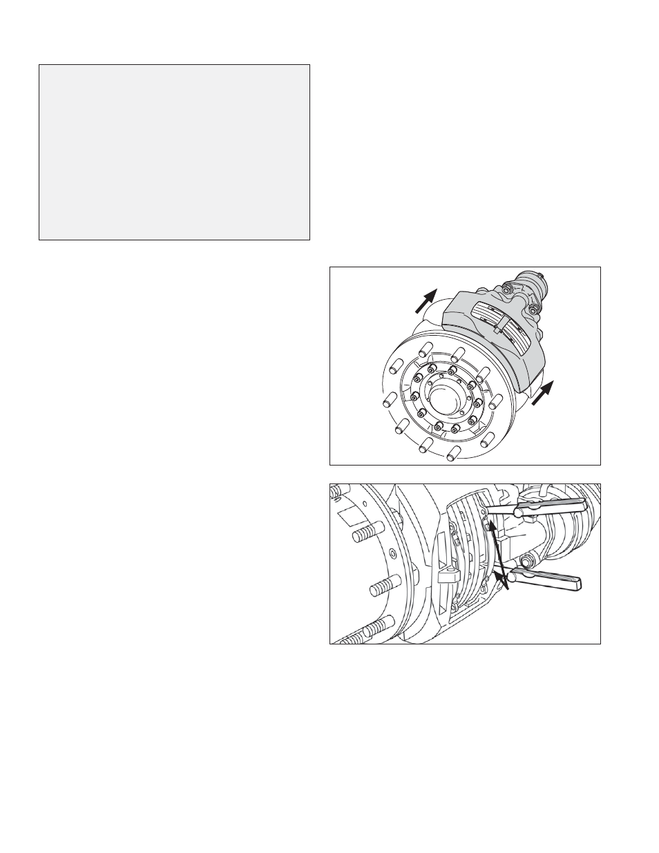
4.1 CALIPER MOVEMENT TEST
CAUTION: Follow all safe maintenance practices.
Remove the wheel. With the spring brakes released or
caged, push the caliper assembly inboard on its guide pins.
Note: To fully release the spring brakes, assure that the
air system pressure is at least 90 PSI. Using a suitable
tool (for example a large fl at-blade screwdriver), press the
inboard pad (12) away from the tappets. Check that there
is no dirt, etc. in the gap, and clean if necessary. Then use
two long-blade feeler gauges to measure over the whole
tappet surface the gap between them and the inboard pad
backplate. (See Figure 16.) The gap should be between
0.024 in. (0.6 mm) and 0.043 in. (1.1 mm).
If the gap is
within the range given, the test is complete.
Pull
Caliper
Inboard
FIGURE 15 - PULL CALIPER INBOARD
Check the clearance at
both tappets simultaneously:
0.024 in. to 0.043 in.
(0.6 mm. to 1.1 mm.)
FIGURE 16 - RUNNING CLEARANCE CHECK
CAUTION: If the clearance is too wide, there is a
danger of brake failure. If the clearance is too small,
or if there is no gap at all, there is a danger of the brake
overheating. These conditions must be corrected
before returning the vehicle to service.
For further investigation, where there is some gap, go to
Section 4.2 and check the adjuster mechanism. Where
there is no movement at all (and so no gap to measure),
go to Section 4.5 “Guide Pin Inspection.”