Bendix Commercial Vehicle Systems WINGMAN ADVANCED FLR20 SENSOR User Manual
Page 43
43
Appendix D
Bendix FLR20 Radar Dynamic Alignment Method
This procedure may be used in rare cases where the stored alignment value is not
available. The vehicle must have a DIU with a software version 12.220 or above.
LATERAL ALIGNMENT USING THE DYNAMIC ALIGNMENT METHOD
Use the flowchart B1 to be sure you are using the correct alignment procedure. This procedure is used in
the rare cases where a learned alignment value is not available. For example, in cases where a technician
erroneously resets the alignment value before recording the Learned Alignment correction value and direction.
D1.1 Tools needed: DIU (with software version 12.220 or above), and a Torx T-20 Screwdriver. The assistance of
another vehicle will be necessary, and an assistant in the cab of the vehicle with the driver.
The DIU’s software version can be seen in the top right-hand corner of the Volume screen. The Bendix DIU’s
Dynamic Alignment Screen is used to show a dynamic calculation of the alignment of the radar.
D1.2 To perform the inspection, the vehicle must be traveling behind a cooperative vehicle on a straight, level length
of highway. Obeying all traffic laws, follow the vehicle in the same lane at a speed greater than 35 MPH.
For the most accurate results, the distance between the vehicles must be between 50 and 300 feet (15 to 91
meters), so the observed distance figure, displayed in the top left-hand corner of the display helps the driver
maintain the correct range. Verify that both vehicles remain in the middle of the lane during the test. The radar
determines the distance and alignment to the vehicle ahead, and, if needed, calculates an alignment correction
value, displayed on the screen.
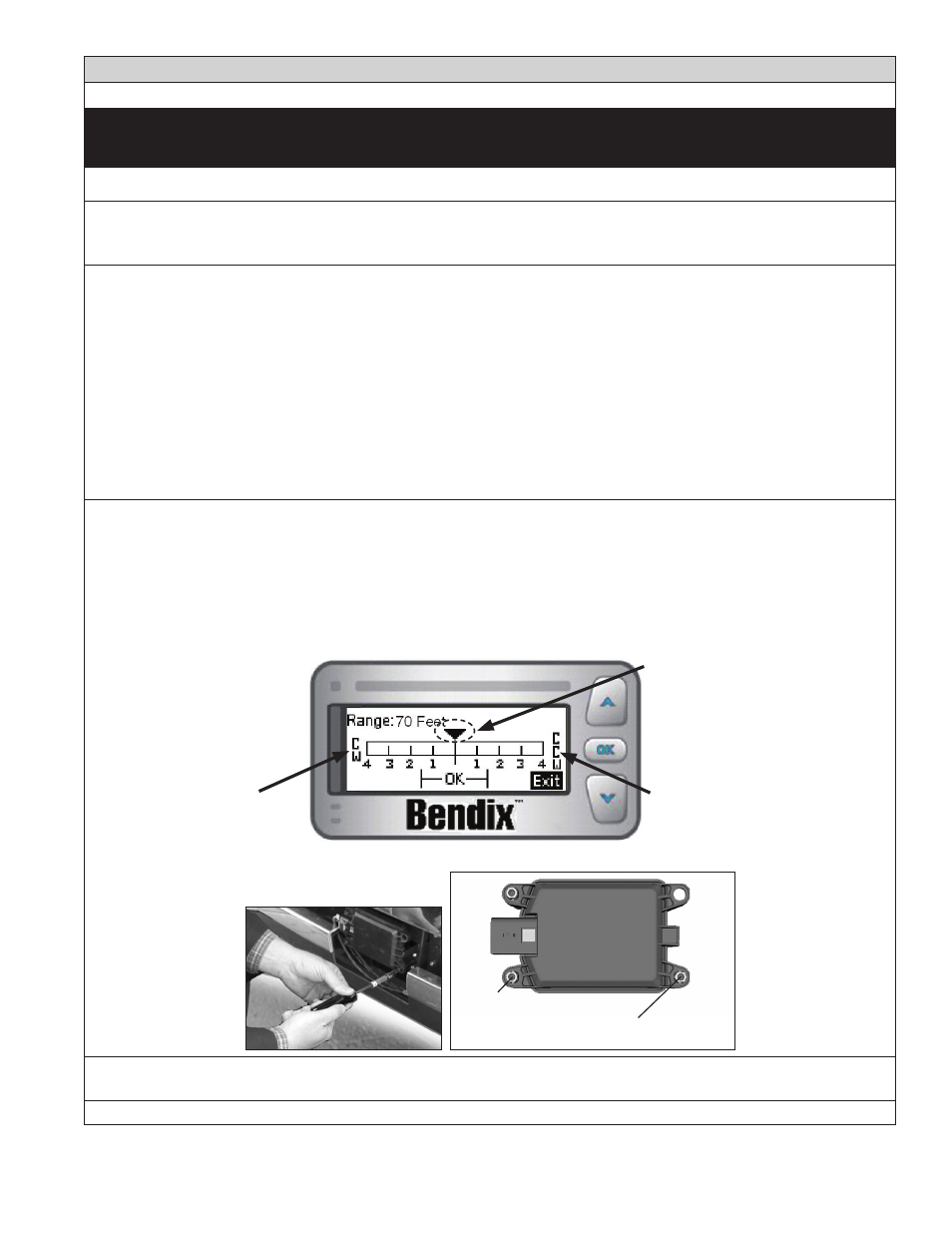
D1.3 During the test, an assistant in the vehicle should observe where on the scale the triangle indicator shows the
alignment correction value. Because this is a dynamic measurement, the arrow will typically move through
a range of positions. Note the average position where the triangle points over a length of time. This value
gives the number of turns of the lateral adjust screw clockwise (CW) or counterclockwise (CCW), in order to
correct any misalignment present. See Figure below. The number of turns may require less than a full screw
turn, e.g. half way between 2 and 3 is 2.5 turns. The scale to the left of center shows when a clockwise (CW)
adjustment is needed, and numbers to the right are for counterclockwise (CCW) adjustments.
CW = Clockwise
CCW = Counterclockwise
The indicator triangle will move
along the scale to show the
number and direction of turns to
make of the adjustment screw.
Dynamic Alignment Screen
Use a Torx T-20 screwdriver here to
adjust for the
lateral alignment
IMPORTANT:
Do not adjust
this stand-off!!
D1.4 Alignment values less than 1.5 from the center are acceptable and do not necessarily require adjustment.
(See the “OK” zone shown on the scale for this range).
Call the Bendix Tech Team at 1-800-AIR-BRAKE (1-800-247-2725, option 2) for troubleshooting assistance.
Appendix D