Bendix Commercial Vehicle Systems GEN 5 ABS User Manual
Page 36
36
ATC Valve Removal
CAUTION: Block wheels before beginning this procedure.
Follow all standard safety procedures, outlined by, but not
limited to, the General Precautions listed on page 13 of
this document.
1. Disconnect the wiring connector from the ATC valve.
2. Disconnect the air lines from the supply (port 1) and
delivery port (port 2) and treadle (port 3) of the ATC
valve.
3. Disconnect the valve mounting fasteners, and remove
the valve.
Installation
1. Install the ATC valve. Torque fasteners to manufacturers
specification.
2. Connect Air lines supply (port 1) delivery port (port 2)
and treadle (port 3) of the ATC valve.
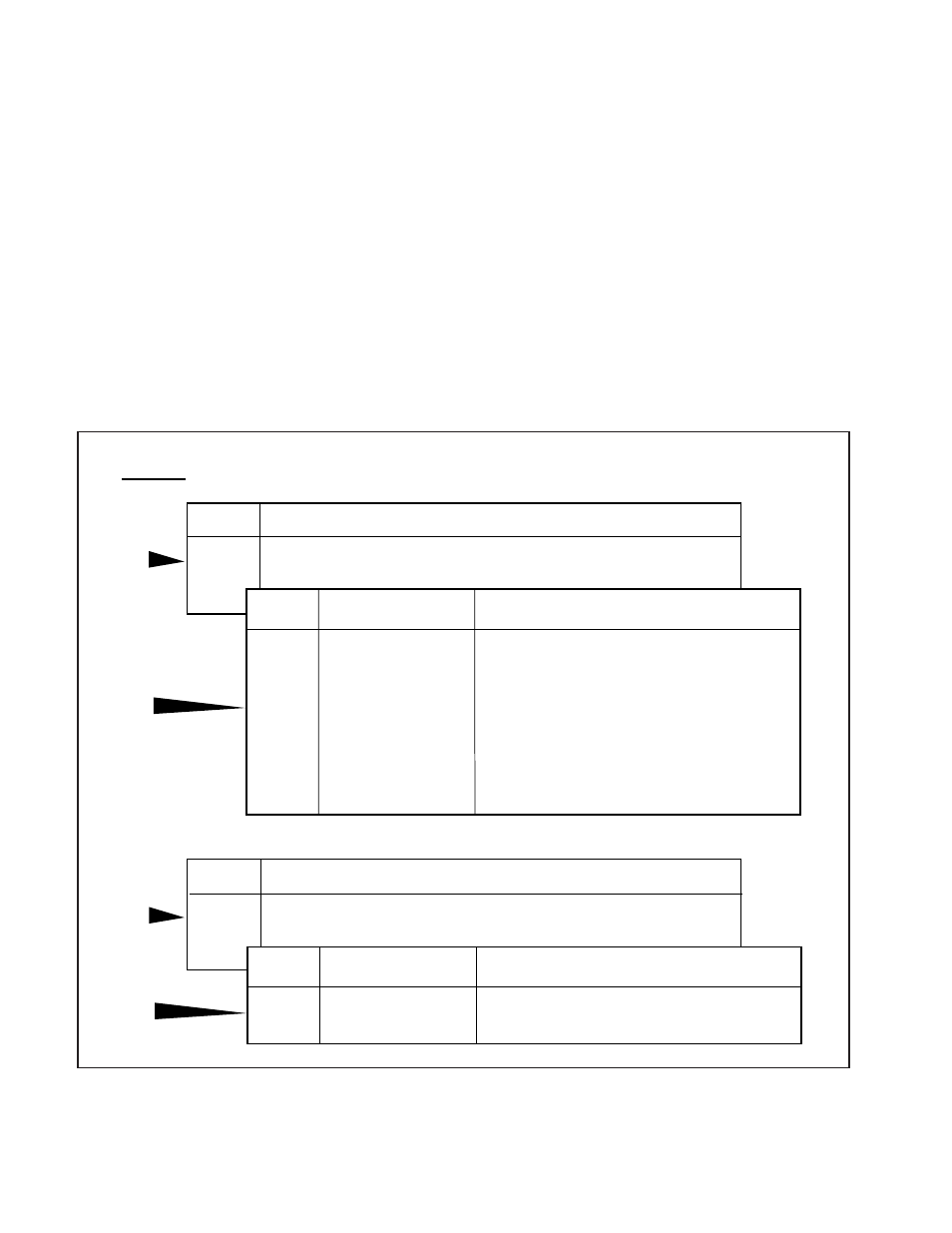
FIGURE 37 - System and ECU Diagnostic Trouble Codes Troubleshooting Guide
1st
1st
2nd
1.5 Sec.
Pause
Location
ECU, Engine Interface
Action
Refer to electrical schematic. Check for proper connection of data link to ECU.
Verify that polarity is correct.
Unplug connector at ECU. There should be a voltage between 0 and 2.5 volts on
J1922/J1939 (–) and a voltage between 2.5 and 5 volts on J1922/J1939 (+).
If vehicle is not equipped with J1922/J1939 engine link, use diagnostic tool to
reconfigure ECU.
Condition
No connection found to engine data
link (J1922/J1939).
Flashes
14
Blink Code
Sequence
2nd
1.5 Sec.
Pause
Location
ECU
Action
If fault cannot be cleared, replace ECU.
Condition
ECU Internal Fault
Flashes
15
Flashes
1–11
Flashes
12
3. Install the wiring connector to the ATC valve.
4. Test the installation.
• Traction Control Valve – Leak Test:
Make and hold brake application. No audible air leaks are
permitted.
• Traction Control Valve Component Test with Hand-
Held Diagnostic Tool:
Select Traction Control Valve
Verify Traction control light operation
Drive the vehicle and verify ABS indicator lamp operates
properly.
CAUTION: Do not start and engage the transmission with
one wheel raised from the floor. With ATC, power will go to
the wheel on the floor and cause the vehicle to move. See
page 20 to disable ATC for dyno testing.