Bendix Commercial Vehicle Systems GEN 5 ABS User Manual
Page 34
34
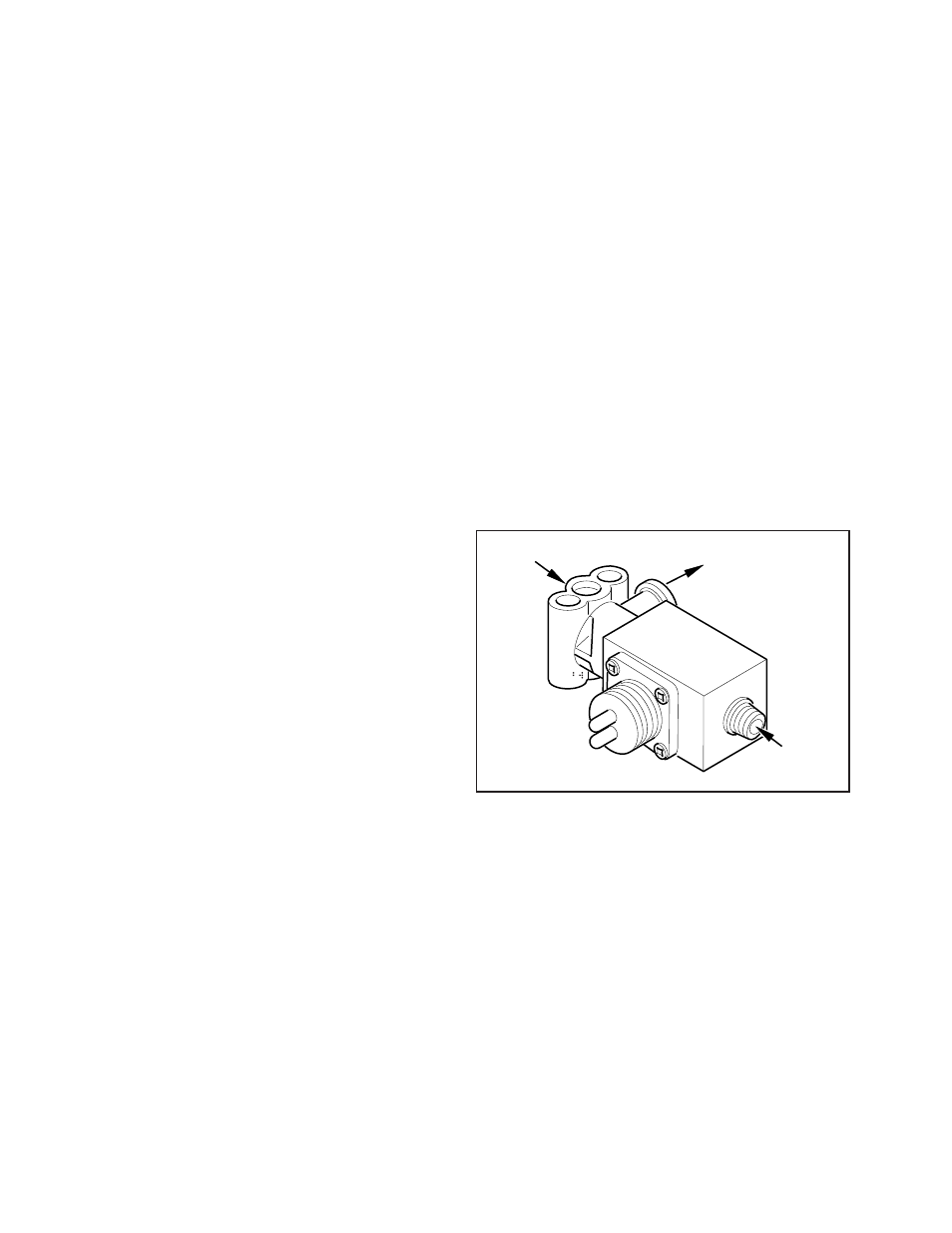
FIGURE 34 - ATC Valve
Performance Test of the Relay Valve
CAUTION: Block wheels before beginning this procedure.
Follow all standard safety procedures, outlined by, but not
limited to, the General Precautions listed on page 13 of
this document.
1. Park vehicle on level surface and block wheels.
2. Release parking brake and fully charge the air system
(governor cut out point).
3. Turn the engine OFF. Apply the service brake several
times, then hold and check for prompt brake air chamber
application and release at all wheels.
4. Apply brake, then hold. Coat outside of relay valve
(where cover joins body) and connection between
modulator valve and relay valve with a soap solution.
No leakage is permitted.
5. If a sluggish response is noted at all wheels, inspect for
kinked or obstructed air line leading to or from valve.
6. Increase system air pressure to governor cutoff. With
the brakes released, coat exhaust port of relay valve
with a soap solution. Leakage of a 1" bubble in 5
seconds is permissible.
7. Depress foot valve and keep depressed. Coat exhaust
port with a soap solution. Leakage of a 1" bubble in 3
seconds is permissible.
Automatic Traction Control (ATC) Valve
Troubleshooting
The following ATC troubleshooting pages provide the basic
information necessary to: identify the diagnostic trouble
code; locate the problem; review the possible cause(s);
select the correct solution and utilize proper repair
procedures.
Follow the steps listed below to locate and correct ATC
problems.
1. Access active diagnostic trouble code(s) using either
the Blink Code procedure or the hand-held tester
procedure.
2. Lookup the code description, the possible causes and
the repair procedures provided in this section.
3. Perform the recommended repair procedures.
4. After the repairs are completed, clear all codes and
check for any additional codes.
Whether the ATC Valve is used as a stand-alone valve as
shown in Figure 34 or is integrated into the cover of a relay
valve as shown in Figure 33, the troubleshooting procedure
is the same.
(3) Treadle
(1) Tank Air
(2) Relay valve
control line