1st 2nd blink code sequence 1.5 second pause – Bendix Commercial Vehicle Systems GEN 5 ABS User Manual
Page 35
35
F
au
lt C
o
d
es
FIGURE 36 - ATC Diagnostic Trouble Code Troubleshooting Guide
1st
2nd
Blink Code
Sequence
1.5 Second
Pause
Location
ATC Valve
Response
Use multimeter to check that valve resistances are correct (fig 34).
If valve is OK check harness for open in wiring.
Use multimeter to check that valve resistances are correct (fig 34).
If valve is OK check harness for open in wiring.
Use multimeter to check that valve resistances are correct (fig 34).
If valve is OK check harness for open in wiring.
Verify proper system configuration and components. Clear faults.
If error cannot be cleared or recurs, replace ECU.
Condition
Solenoid in ATC valve shorted high.
Solenoid in ATC valve shorted to
ground.
ATC valve open circuit.
ATC valve found when it should not
be present.
Flashes
5
6
7
8
Flashes
14
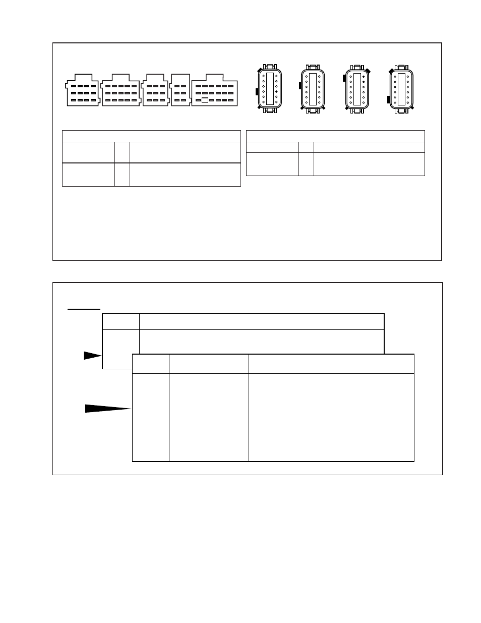
FIGURE 35 - ATC Harness Circuit Descriptions and Resistance Test
Harness Connector
PIN
Circuit Description
X1 (Grey)
3
ATCL (ATC Light/ATC Switch)
X3 (Green)
5
ATC Valve –
6
ATC valve +
Harness Connector
PIN
Circuit Description
A (18-Way)
6
ATC Mud and Snow Switch
16
ATCL (ATC Light)
D (15-Way)
4
ATC Valve +
7
ATC Valve –
ATC Valve Resistance Test
The correct resistance for the ATC Valve circuit is between 9 ohms and 15 ohms.
Measure resistance at the ATC Valve to check the valve.
Measure resistance at the appropriate ECU harness connector pins to check the cable and valve.
Note: Refer to the chart for pin identification.
X2 Black
X3 Green
7
8
9
10
11
12
6
5
4
3
2
1
7
8
9
10
11
12
6
5
4
3
2
1
X4 Brown
7
8
9
10
11
12
6
5
4
3
2
1
X1 Grey
7
8
9
10
11
12
6
5
4
3
2
1
A
B
C
D
E
10
11
12
7
8
9
4
5
6
1
2
3
10
11
12
13
14
15
13
14
15
16
17
18
7
8
9
4
5
6
1
2
3
10
11
12
7
8
9
4
5
6
1
2
3
7
8
9
4
5
6
1
2
3
4
5
6
1
2
3
TOP – Looking into harness connector
Cab Mount
Frame Mount