Bendix Commercial Vehicle Systems GEN 5 ABS User Manual
Page 2
2
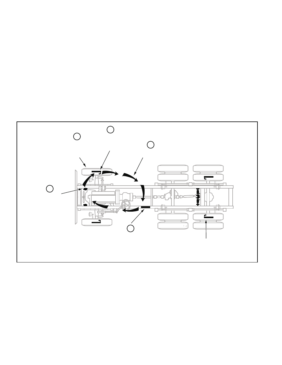
FIGURE 2 - Overview of ABS Operation
ANTILOCK BRAKING SYSTEM (ABS)
ABS-controlled braking ensures optimum vehicle stability
while minimizing the stopping distance. During vehicle
operation, the ABS Electronic Control Unit (ECU)
continuously monitors all wheel speed sensors. Data input
from the wheel speed sensors allows the ECU to:
•
Detect impending wheel lock.
•
Maintain optimum wheel slip during braking.
•
Maximize vehicle stability while maintaining braking
effectiveness.
ABS Operation
The ABS controls braking by operating the Pressure
Modulator Valves. The ECU makes a new assessment of
conditions and updates the control signal to the pressure
modulator valves at the rate of 100 times per second.
Speed sensors
monitor wheel
rotation
1
Speed signal
to ECU
Electronic Control Unit (ECU)
interprets speed signals
and activates valves
Hold and release
solenoids control
air pressure in the
brake chambers
Sensors on
all configured wheels
signal status to ECU
Braking force
remains at
optimum level
2
3
4
5
When inactive, the pressure modulator valves provide
straight-through-passages for supply air to the brake
chambers. During ABS operation (an ABS “event”), the
control unit operates the valves to override the supply of
air to the chambers. During an ABS release, supply air is
held off while the chambers are vented to the atmosphere.
In hold mode, supply air is held off and chamber air is held
constant. When required, air is applied to the chamber at
a controlled rate by modulating the hold side of the
modulator valve.
The ABS system itself does not apply additional braking
power. Rather, the purpose of ABS is to limit brake torque
to prevent locking that results in loss of lateral stability and
increased stopping distances. Cautious driving practices
such as maintaining adequate distances from the vehicle
ahead are still essential to safe vehicle operation.