Abs operation, Axle control, Dolly-axle control (select low) – Bendix Commercial Vehicle Systems MC-30 TRAILER ABS CONTROLLER User Manual
Page 7: Steer axle option (mod2 select low), Side control, Normal braking, Diagnostic led display of confi guration, Modulator chuff test at power-up
7
ABS OPERATION
The MC-30
™
controller uses wheel speed sensors, ABS
modulator-valves and an ECU to control trailer wheels by
axle or by side. By detecting excessive wheel slip during
braking and adjusting the pressure to each brake chamber,
the MC-30
™
controller is able to optimize slip between the
tire and the road surface. The EC-30T
™
controller controls
the ABS modulator-valves, similar to a driver pumping the
brakes. However, the MC-30
™
controller is able to pump the
brakes on the vehicle with greater speed and accuracy.
Axle Control
MC-30
™
controller axle control will utilize a single ABS
modulator-valve to control wheels from both sides of a
given axle or axles. In the case of an unbalanced braking
surface, axle control will control the high coeffi cient wheel
just under the lock limit. Temporary periods of wheel lock
are permitted on the low coeffi cient wheel. Axle control
should not be used on 5th wheel dollies or steerable axles.
When braking on even surfaces, an axle-control system
will perform similar to a side control, two modulator system.
Axle control is available in 2S/1M, 2S/2M and 4S/2M
installations.
Dolly-Axle Control (Select Low)
MC-30
™
controller dolly-axle control will utilize a single
ABS modulator-valve to control wheels from both sides of
a given axle or axles. In the case of an unbalanced braking
surface, dolly-axle control will control the low coeffi cient
wheel just under the lock limit. Optimal vehicle stability
is achieved by not allowing the high coeffi cient wheel to
sustain wheel lock. When braking on even surfaces, a dolly
axle control system will perform similar to side control or
axle control system. Dolly axle control is only available in
2S/1M installations.
Steer Axle Option (MOD2 Select Low)
This option causes MOD2 to be Dolly-Axle controlled and
is only active while confi gured for 4S/2M Axle control. This
confi guration option should be set when MOD2 is installed
on a forward or steer axle of a full trailer. Steer Axle option
can be set using a diagnostic tool or by purchasing an
MC-30
™
controller unit with this option pre-set.
Side Control
The MC-30
™
controller will utilize a single ABS modulator-
valve to control one or more wheels on a given vehicle side.
In the case of an unbalanced braking surface, MC-30
™
controller side control will individually control each side just
under the lock limit. Side control is available in 2S/2M and
4S/2M installations.
Normal Braking
During normal braking, the MC-30
™
controller functions as
a standard relay valve. As brakes are applied or released
by the driver, the control signal from the tractor foot valve
causes the M-30T
™
modulator-valve to apply proportional
pressure to the trailer brake chambers.
If a PLC tractor and PLC trailer are powered at the same
time, the MC-30
™
controller will also trigger a bulb check
on the tractor dash using PLC.
Diagnostic LED Display of Confi guration
At power-up, the diagnostic LEDs all illuminate, then display
the current confi guration for sensors, modulators and ABS
control. See chart 3. After displaying the confi guration,
only the green VLT LED will stay on. However, if a fault is
detected, the faulted component will be displayed by the
red diagnostic LEDs.
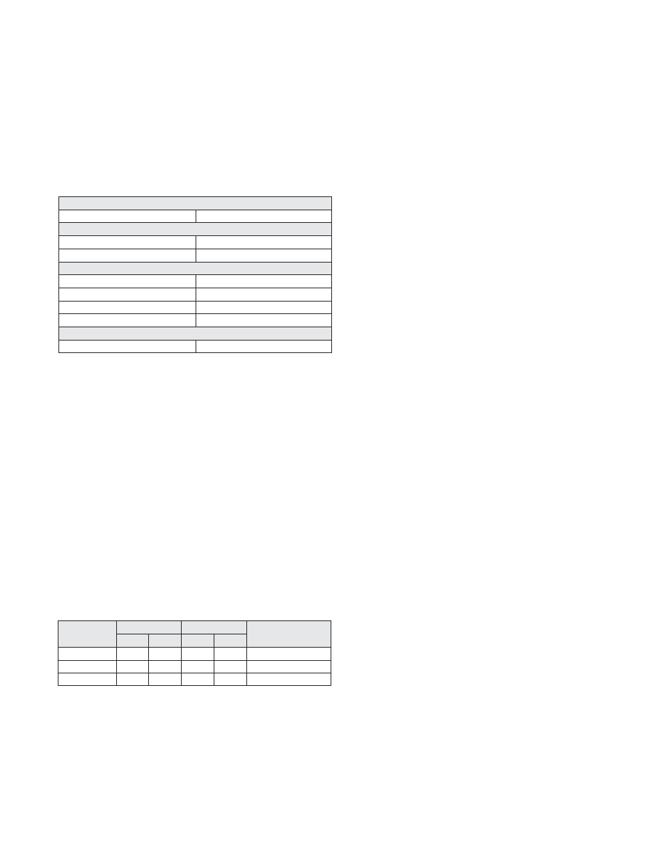
CHART 4 - MC-30
™
CONTROLLER ABS CONFIGURATIONS
System
Sensors Modulators Available
Confi
guration
2 4 1 2
ABS
Control
Settings
2S/1M
X X Axle
or
Dolly-Axle
2S/2M X X Axle
or
Side
4S/2M X X Axle
or
Side
CHART 3 - LED POWER-UP SEQUENCE
MC-30
™
Controller – LED Power-Up Sequence
At
power-up All
LEDs
1st blink displays number of wheel speed sensors
2
Sensors
SEN-FRT
4
Sensors
SEN-RER-FRT
2nd blink displays modulator confi guration
1 Modulator (Dolly-Axle control)
MOD
1 Modulator (Axle control)
MOD-FRT
2 Modulators (Axle control)
MOD-RER-FRT
2 Modulators (Side control)
MOD-LFT-RHT
Normal Operation
No Faults
VLT (green) LED illuminated only
Modulator Chuff Test at Power-Up
At power-up, the MC-30
™
controller activates a modulator
chuff test. This electrical and pneumatic ABS modulator
test can assist the technician in verifying that the modulator
wiring and installation are correct. With brake pressure
applied, a properly installed modulator will cause fi ve
rapid audible chuffs of air pressure. If two modulators
are installed, the MC-30
™
controller activates 5 chuffs at
Modulator 1 (MOD 1) then Modulator 2 (MOD2). The chuff
sequence is then repeated.
If the modulator is wired incorrectly, the modulator will only
produce one chuff, or no chuff at all. If an issue is detected
during the modulator chuff test, compare the modulator
wiring and plumbing to the MC-30
™
controller’s electrical
system schematic and make repairs. See Figures 16 and
17.