Mc-30, Controller diagnostic display, Blink code diagnostics – Bendix Commercial Vehicle Systems MC-30 TRAILER ABS CONTROLLER User Manual
Page 12
12
MC-30
™
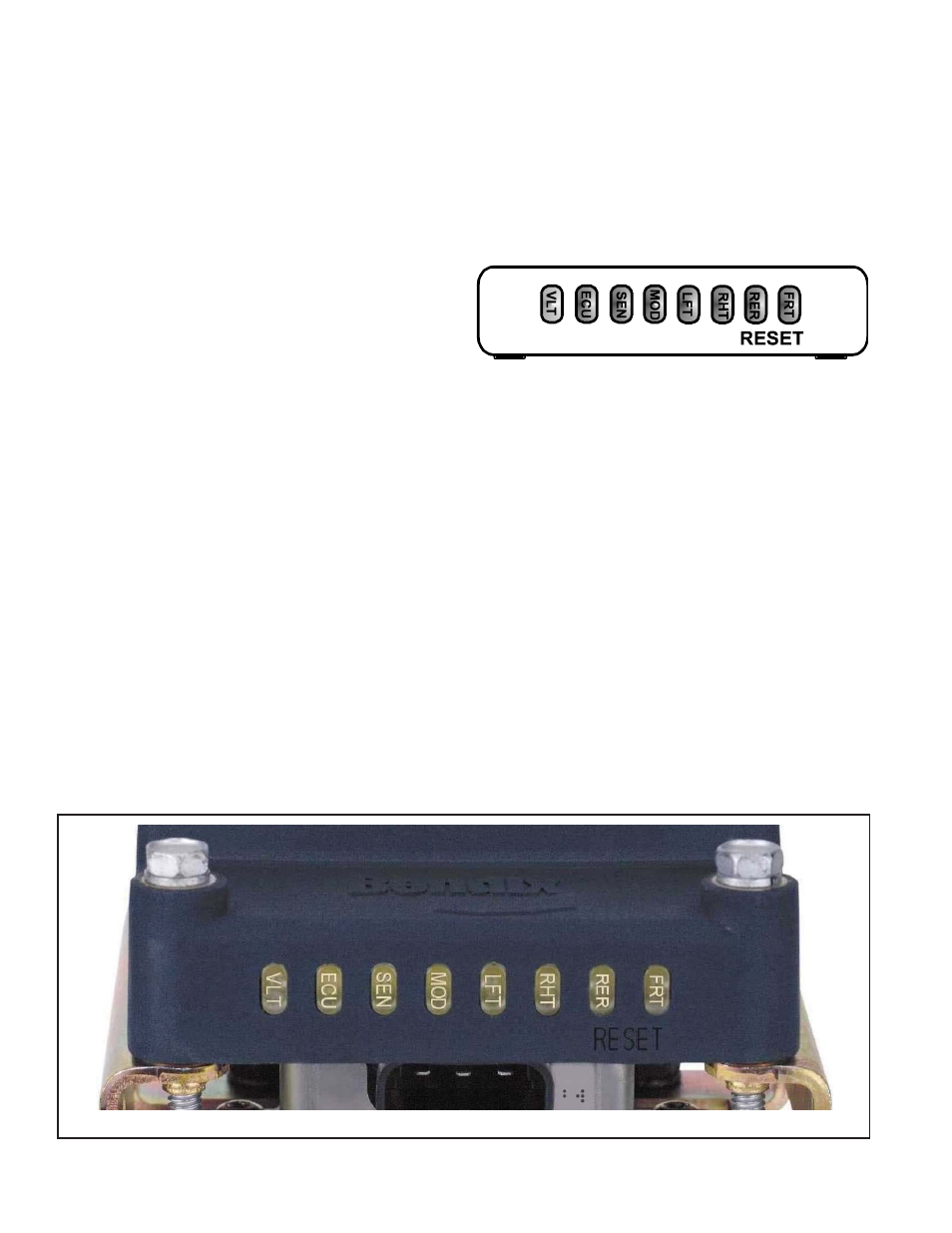
CONTROLLER DIAGNOSTIC DISPLAY
The MC-30
™
controller diagnostic display consists of seven
red fault LEDs, one green power LED and an internal
magnetic reset switch. See Figure 13 for illustration.
No diagnostic tools are needed to read the MC-30
™
controller’s diagnostic display. A fault displayed on the
LEDs will always cause the ABS indicator lamp to be on.
Reading a Fault
When a fault is detected, the MC-30
™
controller identifi es
the faulted component with the diagnostic LEDs. A wheel
speed sensor or modulator LED (SEN or MOD) may be
accompanied by wheel location LEDs. An example is
FRT-RHT-SEN. When these three LEDs are on, this is
an indication of a fault on the front axle (FRT), right side
(RHT), wheel speed sensor (SEN).
For complete explanation and troubleshooting of faults
displayed by the LEDs, go to section E, Troubleshooting.
The red diagnostic LEDs only indicate active system faults.
When a fault self-heals or is manually reset, the LEDs are
cleared but the fault code remains in fault history. Fault
history can be retrieved with blink code diagnostics or with
a diagnostic tool.
If faults occur on multiple components, the diagnostic
LEDs will display one fault at a time. When the fi rst fault is
repaired and the MC-30
™
controller is reset, the next fault
will be displayed on the LEDs.
Fault Reset
After the fault is corrected, the active fault code and LEDs
can be reset by briefl y holding a magnet in place at the
RESET location of the diagnostic display. See Figure
13. All of the LEDs will be on while the magnet is held in
place. If one or more of the LEDs do not go on when the
magnet is in place, replace the EC-30T
™
controller. When
the magnet is removed from the reset location, only the
green VLT diagnostic LED should be on. However, if any
red LEDs are still on, active faults are still present in the
system.
Note: A self-confi guration will occur if the magnet is held
at the reset location for greater than 20 seconds. Do not
hold the magnet at the reset location for longer than 10
seconds unless a self-confi guration is desired.
FIGURE 13 - MC-30
™
CONTROLLER LED DIAGNOSTIC DISPLAY
FIGURE 14 - MC-30
™
CONTROLLER LED DIAGNOSTIC
DISPLAY
BLINK CODE DIAGNOSTICS
The MC-30
™
controller provides diagnostic and confi guration
functions through blink code diagnostics. Blink code
diagnostics are activated by providing constant power to
the ignition circuit and toggling the brake light power input
to the MC-30
™
controller.
When blink code mode is activated, the MC-30
™
controller
will blink the trailer mounted ABS indicator lamp to display
active fault codes, fault code history, ABS confi gurations
and odometer mileage. Blink code diagnostics can also be
used to reset active fault codes. See chart 9 for all blink
code functions.
Following a single display of all available messages, the
ABS indicator lamp will remain on for fi ve seconds and
then return to normal operating mode.