Troubleshooting – Bendix Commercial Vehicle Systems EC-14 ANTILOCK CONTROLLER 5/04 User Manual
Page 23
23
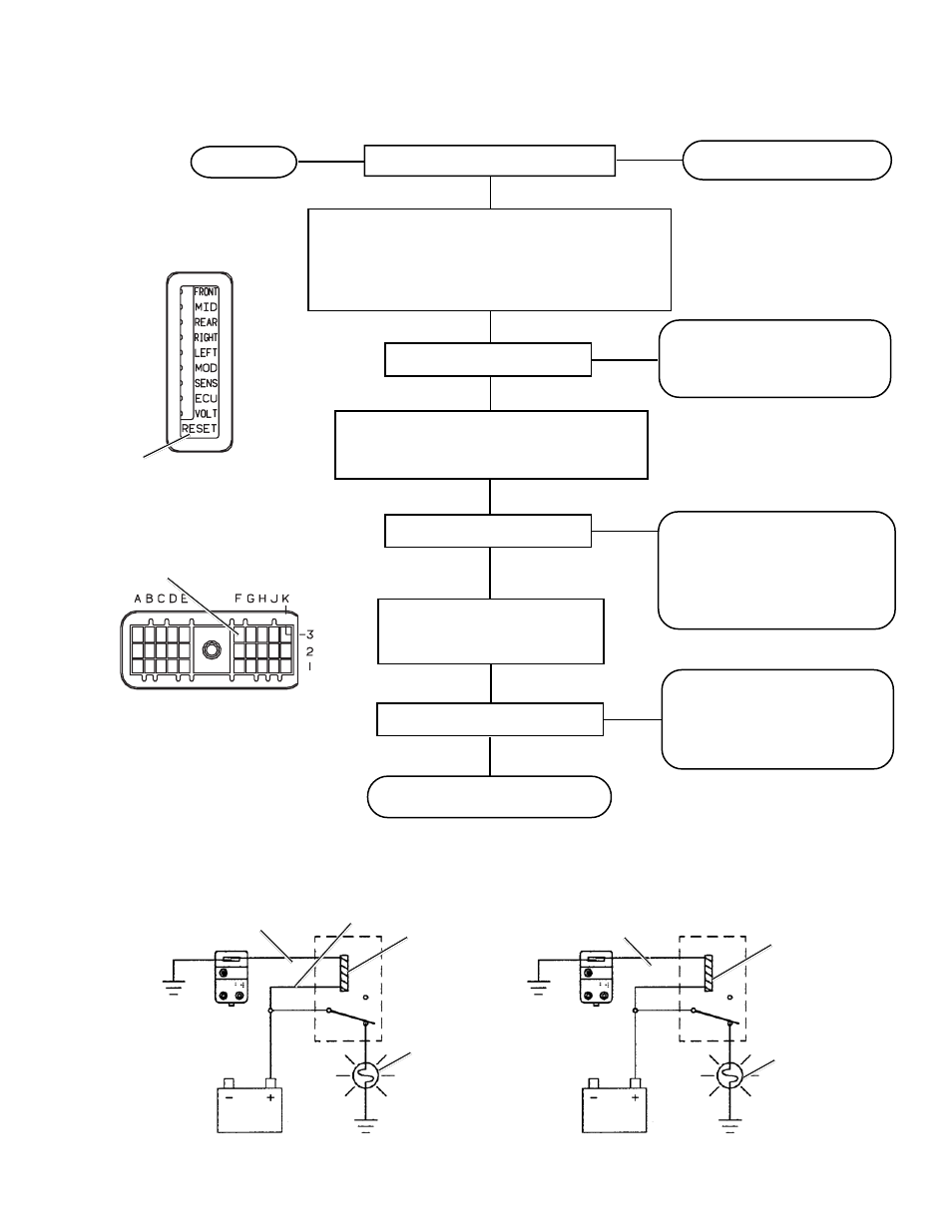
Is continuity detected?
Are all LEDs illuminated?
Remove magnet from EC-14
™
controller, turn ignition
off and disconnect the wiring harness connector(s)
from EC-14
™
controller. Check continuity of warning
lamp wire between EC-14
™
controller wiring harness
connector pin 3F and terminal on lamp relay.
Repair or replace wire harness,
reconnect EC-14
™
controller wire
harness and repeat the “Initial
Start-up Procedure”
Reconnect EC-14
™
controller wire harness
connector, turn ignition on and check for
vehicle power at the lamp relay coil
Is power detected?
Check dash wiring and
connectors, and consult the vehicle
manual for troubleshooting
information. Repair or replace as
necessary and repeat the “Initial
Start-up Procedure”
Repeat the “Initial Start-up
Procedure.” If testing has
returned to this step twice
replace the EC-14
™
controller
and retest.
YES
NO
YES
Is dash lamp on?
Replace the relay and repeat
“Initial Start-up Procedure”
TROUBLESHOOTING
SECTION IX
TESTING FOR FALSE INDICATION CAUSED BY DASH LIGHT RELAY
TESTING
EC-14
™
CONTROLLER
LEDs
NO
YES
Replace the EC-14
™
controller
NO
YES
NO
Connect the opposite end of relay
coil to vehicle ground and not
reaction of dash lamp
EC-14
™
Controller
Wire Harness Connector
3F Lamp Relay
MAGNET
HERE
START HERE
TESTING THE LAMP RELAY
CHECK FOR
POWER HERE
COIL
RELAY
LAMP
WIRE 3F FROM
MC-14
™
MODULATOR
CONTROLLER
VEHICLE POWER
MC-14
™
MODULATOR
CONTROLLER
RELAY
LAMP ON?
BAD RELAY
GROUND THIS
WIRE
VEHICLE POWER
MC-14
™
MODULATOR
CONTROLLER
COIL