Bendix Commercial Vehicle Systems EC-14 ANTILOCK CONTROLLER 5/04 User Manual
Page 10
10
the entire antilock system including wiring continuity. A dash
lamp, controlled by the EC-14
™
controller, advises the driver
of the condition of the entire antilock system. The condition
of specific antilock components is provided to the mechanic
by a series of labeled, light emitting diodes (LED’s) displayed
through a “window” in the EC-14
™
controller housing. No
special tools or equipment are needed to read or interpret
the EC-14
™
controller diagnostics window. It should be noted
that the diagnostics display is separate from the antilock
condition lamp on the dash. With this separation, the driver
is aware of any problems that occur, but is not concerned
with in-depth diagnostic information.
A special feature of the EC-14
™
controller diagnostic system
is its failure latching. Intermittent problems, particularly in
the wheel speed sensing area can be difficult to diagnose.
When the controller senses an erroneous condition, whether
in the controller electronics, the modulator or speed sensing
areas, it stores the condition in non-volatile memory, disables
the antilock function if necessary, illuminates the dash
mounted antilock condition lamp and the appropriate
diagnostic LEDs on the EC-14
™
controller. The malfunction
condition is truly stored and is not cleared by loss of power
to the EC-14
™
controller. The LEDs will re-light when power
is restored and remain illuminated until the problem is
corrected. After the actual problem is corrected, maintenance
personnel can clear or reset the EC-14
™
controller
diagnostics by passing a small magnet over the RESET
point in the diagnostics window.
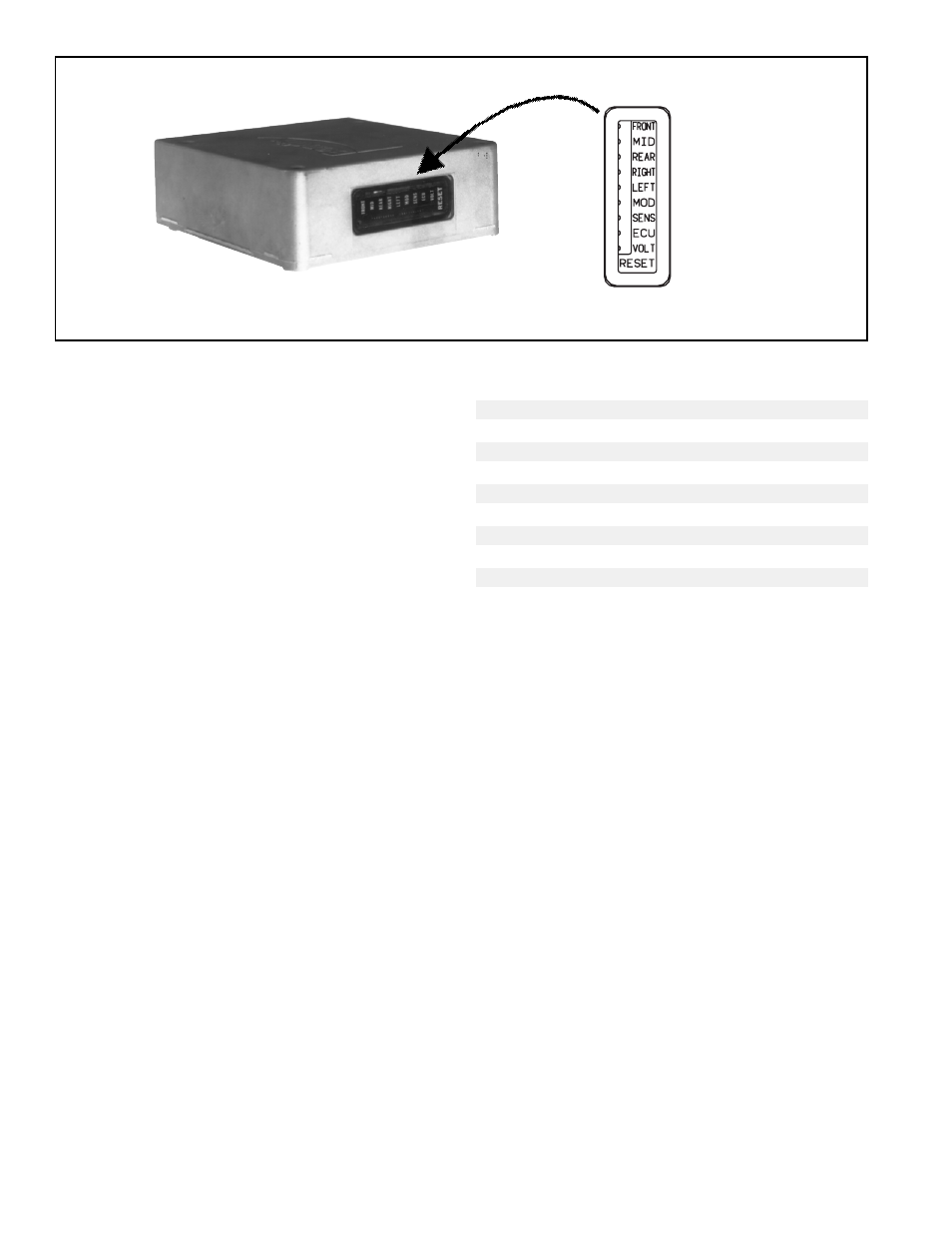
DIAGNOSTIC LEDS
There are nine LEDs plus a magnetically actuated reset
switch in the EC-14
™
controller diagnostic window. The first
five LEDs locate a problem to a specific area of the trailer
while the last four indicate the problem component or its
wiring. The LEDs are computer controlled and are either ON
or OFF depending upon their monitor function. (Note: Right
and left, front and rear are determined from the driver's seat.
Left front is therefore the corner closest to the driver.)
LED
o FRONT Red LED
LED
o MID
Red LED (SEE NOTE)
LED
o REAR
Red LED
LED
o RIGHT Red LED
LED
o LEFT
Red LED
LED
o MOD
Red LED
LED
o SENS Red LED
LED
o ECU
Red LED
LED
o VOLT
Green LED
¦ ¦ ¦
RESET
No LED
Note:
The MID LED shown in the chart above is not used
in the diagnostic process for the EC-14
™
controller
however, it will light when a magnet is placed on the
RESET switch in the diagnostic window.
"FRONT" LED
This Red LED illuminates and latches on in order to indicate
the location of a problem component or its wiring. It will light
in conjunction with either the RIGHT or LEFT LED and the
SENS LED when indicating a speed sensor problem. The
FRONT LED will also light in conjunction with the MOD LED
to indicate that the front modulator (M-21
™
or M-22
™
) or its
wiring has malfunctioned.
"MID" LED
This red LED is not used in troubleshooting the EC-14
™
controller and should light only when a magnet is held on
the RESET switch.
"REAR" LED
This red LED illuminates and latches on in order to indicate
the location of a problem component or its wiring. It will light
in conjunction with either the RIGHT or LEFT LED and the
SENS LED when indicating a speed sensor problem. The
REAR LED will also light in conjunction with the MOD LED
to indicate that the rear modulator (M-12
™
) or its wiring has
malfunctioned.
FIGURE 8 - EC-14
™
CONTROLLER DIAGNOSTIC WINDOW