To connect/disconnect vacuum hoses – Wood’s Powr-Grip MRTA611LDC2 User Manual
Page 13
Rev 0.0/4-14
11
MRTA6-DC2: #35072
1) Select a configuration to provide optimal support across the load surface and to minimize load
overhang (see INTENDED USE: L
OAD
C
HARACTERISTICS
).
• To support the maximum load weight, you must install all vacuum pads on the pad frame
(see T
O
I
NSTALL
/R
EMOVE
E
XTENSION
A
RMS AND
R
EPOSITION
V
ACUUM
P
ADS
to follow) and connect
all vacuum hoses to the vacuum pads, using the quick connectors (see discussion below).
5
• To support larger load dimensions, you must also install extension arms on the pad frame
(see T
O
I
NSTALL
/R
EMOVE
E
XTENSION
A
RMS AND
R
EPOSITION
V
ACUUM
P
ADS
to follow).
• To support smaller weights and dimensions, you may remove some extension arms or
vacuum pads, and disconnect the corresponding vacuum hoses,
provided that the lifter
still has sufficient capacity to support the load in question
.
Removing or disconnecting any vacuum pad reduces lifting capacity.
2) Assemble the pad frame in a symmetrical configuration, to keep the lifter balanced (see
illustrations on preceding page).
Make sure all vacuum hoses are positioned to avoid damage during lifter
operation.
3) Make sure all vacuum hoses are secure and routed to avoid being pinched, snagged, abraded
or otherwise damaged during lifter operation.
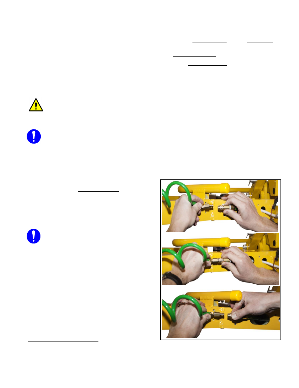
To Connect/Disconnect Vacuum Hoses
To connect a vacuum hose, push the male and
female ends of the quick connector together
until they lock, as shown.
To disconnect the vacuum hose, move the
release ring on the female end until the quick
connector separates, as shown.
Make sure that quick connectors seal
completely and all vacuum
hoses function correctly.
5
Whenever a quick connector is disconnected, the corresponding vacuum pad does not contribute to the lifting capacity,
whether or not the pad is mounted on the pad frame.