2 and figure 4), N 2.1.2 and figure 4) – Vicor PI5101-EVAL1 3.3V/60A High Side Active ORing Evaluation Board User Manual
Page 6
Picor Corporation • picorpower.com
PI5101-EVAL1 User Guide Rev 1.0 Page
6 of 12
Before initial power-up follow these steps to configure
the evaluation board for specific end application
requirement:
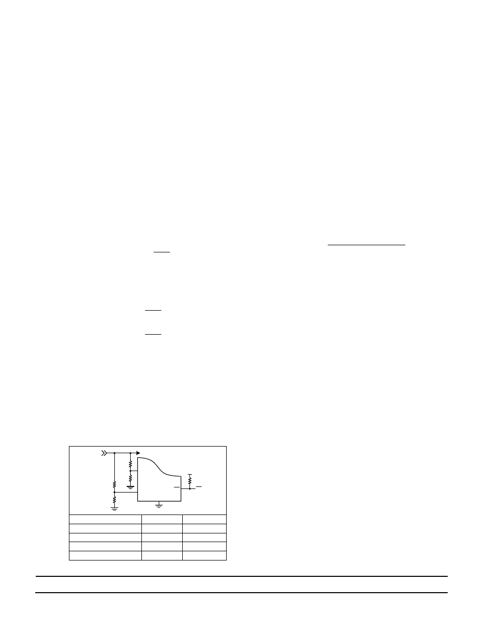
2. UV and OV resistors set up:
2.1. UV and OV programmable resistors are
configured for a 3.3V Vin (BUS voltage)
application in a two-resistor voltage divider
configuration as shown in Figure 4. UV is set to
2.6V and OV is set for 3.8V, R1
OV
and R1
UV
are
2.00KΩ 1%. If the PI5101-EVAL1 is required to
be used with a different Vin voltage application
please follow the following steps to change the
resistor values.
2.1.1. It is important to consider the maximum
current that will flow in the resistor
divider and maximum error due to UV and
OV input current.
2.1.2. Set
and
value based on system
allowable minimum current and 1% error;
Where:
: UV threshold voltage
:
UV voltage set (0.5Vtyp)
:
current
: OV threshold voltage
:
OV voltage set (0.5Vtyp)
:
current
Ref. Desg.
U1
U2
R1
UV
R5
R6
R2
UV
R1
R2
R1
OV
R7
R8
R2
OV
R3
R4
Figure 4: UV & OV two resistor divider configuration
3. Auxiliary Power Supply (Vaux):
3.1. The PI2001 Controller has a separate input (VC)
that provides power to the control circuitry and
the gate driver. An internal voltage regulator
(VC) clamps the VC voltage to 15.5 V typically.
3.2. Connect independent power source to Vaux
inputs of PI5101-EVAL1 Evaluation Board to
supply power to the VC input. The Vaux voltage
should be 5V higher than Vin (redundant power
source output voltage) to fully enhance the
PI5101.
3.3. 10 Ω bias resistors (Rbias, reference designators
R11 and R12) are installed on the PI5101-EVAL1
between each Vaux input and VC pin of the
PI2001 controllers (U1 and U2).
3.4. If Vaux is higher than the Clamp voltage, 15.5 V
typical, the Rbias value has to be changed using
the following equations:
Where:
: Vaux minimum voltage
: Maximum PI2001 VC Clamp Voltage (16V)
: PI2001 maximum Quiescent Current (4.2mA)
Refer to PI2001 Datasheet for more details on Rbias.
4. Hook Up of the Evaluation Board
4.1. OV and UV resistors values are configured for a
3.3 V input. If you are using the evaluation board
at a different input voltage level you have to
adjust the resistor values by replacing R1, R2, R3
and R4, or remove R3, R4, R5 and R6 to disable
UV and OV function.
4.2. Please refer to the UV/OV section for details to
set R1, R2, R3 and R4 proper values.
4.3. Connect the positive terminal of PS1 power
supply to Vin1. Connect the ground terminal of
PS1 to its local Gnd. Set the power supply to 3.3
V. Keep PS1 output disabled (OFF).
4.4. Connect the positive terminal of PS2 power
supply to Vin2. Connect the ground terminal of
PS2 to its local Gnd. Set the power supply to 3.3
V. Keep PS2 output disabled (OFF).
4.5. Connect the positive terminal of PS3 power
supply to Vaux1 and Vaux2. Connect the ground
terminal of this power supply to Gnd. Set the
power supply to 12 V. Keep PS3 output disabled
(OFF).
4.6. Connect the electronic load to the output
between Vout and Gnd. Set the load current to
20 A.
Vin
GND
V_Logic
PI2001
OV
UV
FT
FT
R1
UV
R2
UV
R1
OV
R2
OV
U1/U2