Bill of material – Vicor PI5101-EVAL1 3.3V/60A High Side Active ORing Evaluation Board User Manual
Page 4
Picor Corporation • picorpower.com
PI5101-EVAL1 User Guide Rev 1.0 Page
4 of 12
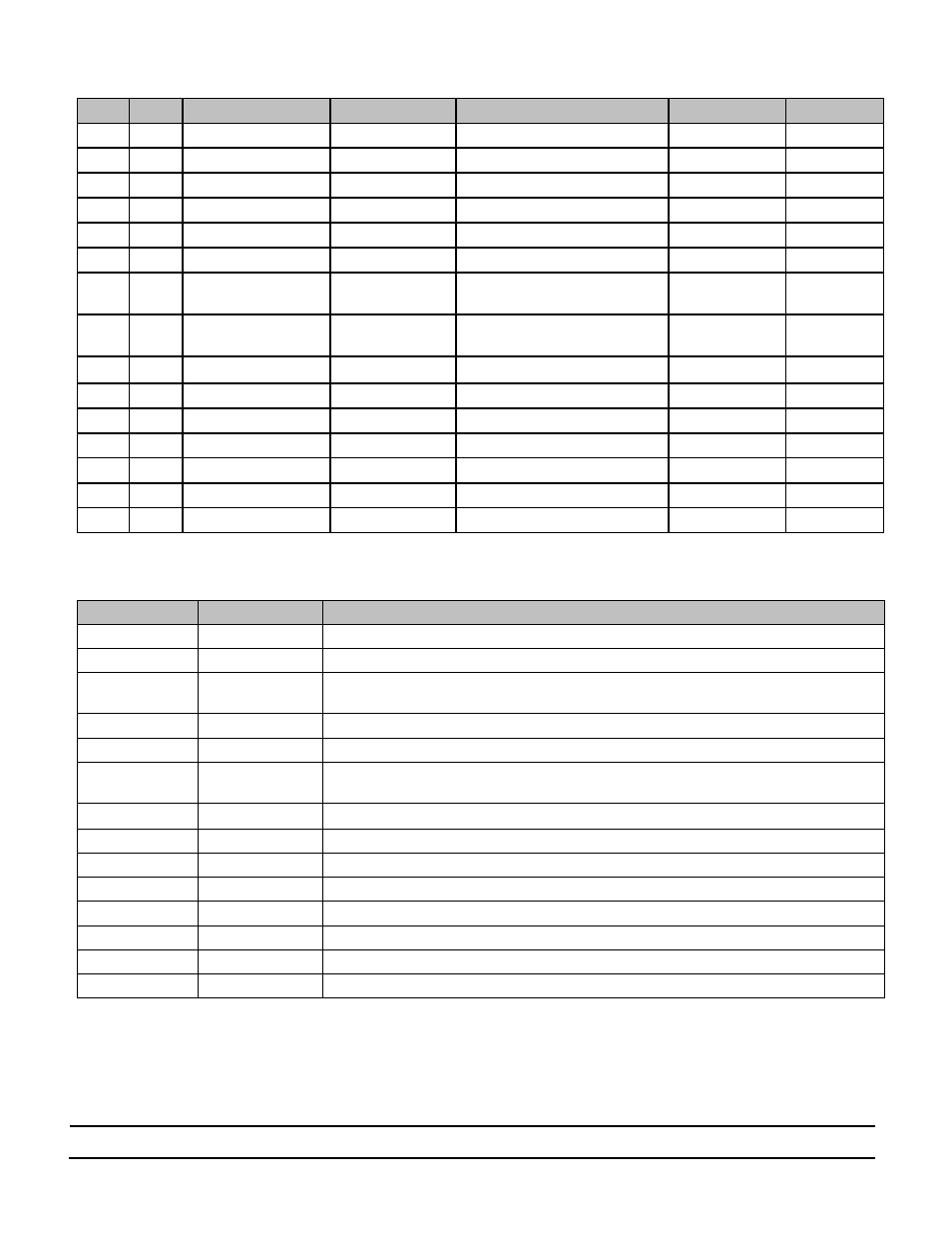
Bill of Material
Item
QTY
Ref. Designator
Value/Part NO.
Description
Footprint
Manufacturer
1
2
C1, C2
1μF
MLCC Capacitor, X5R, 1μF,16V
0603
2
2
C3
22μF
MLCC Capacitor, X5R, 22μF,25V
1210
3
4
C4, C5, C6, C7
Not Installed
1206
4
2
D1, D2
LTST-C191CKT
LED, Red
0603 LED
Lite-On
5
2
D3, D4
BZX384-B5V1,115
Zener Diode 5.1V 300mW
SOD323
NXP
6
2
D5, D6
PMEG3005EJ,115
Schottky Diode, ,30V,500mA
SOD323
NXP
7
10
D1, D2,
1,
2, Gnd,
S1, S2, Vaux1, Vaux2
1528
Turret Test point
TURRET - 1528
Keystone
Electronics
8
16
Gnd, Vin1, Vin2, Vout
1502
Turret Test point
TURRET - 1502
Keystone
Electronics
9
2
M1, M2
PI5101-00-LGIZ
N-MOSFET, 5V, 60A
3-Lead LGA
PICOR
10
2
R1, R2
8.45kΩ
Resistor, 8.45kΩ, 1%,0.1W
0603
11
2
R3, R4
13.3kΩ
Resistor,13.3kΩ, 1%, 0.125W
0603
12
4
R5, R6, R7, R8
2.00kΩ
Resistor, 2.00kΩ, 1%, 0.125W
0603
13
2
R9, R10
4.99kΩ
Resistor, 4.99kΩ,1%,0.1W
0603
14
2
R11, R12
10Ω
Resistor, 10Ω,1%,0.1W
0603
15
2
U1, U2
PI2001-00-QEIG
Picor Cool-ORing Controller IC
3x3mm 10L DFN
PICOR
Table 2: PI5101-EVAL1 Evaluation Board Bill of Materials
Ref. Designator
Value/Part NO.
Functional Description
C1, C2,
1uF
VC Bypass Capacitor
C3
22uF
Output (Load) Capacitor
C4, C5, C6, C7
Not Installed
Snubber to reduce voltage ringing when the device turns off. Add the capacitors if long
harnesses are used to connect the power source or load to the board.
D1, D2
LTST-C191CKT
A fault is indicate exists when the LED is on
D3, D4
BZX384-B5V1,115
Zener diode clamps the gate voltage
D5, D6
PMEG3005EJ,115
Schottky Diode added to prevent current flow from Vin into the controller during gate
discharge
M1, M2
PI5101-00-LGIZ
PICOR ultra-low R
DS(on)
MOSFET
R1, R2
8.45kΩ
UV Voltage Divider Resistor ( R2UV as defined in section 2.1.2 and Figure 4)
R3, R4
13.3kΩ
OV Voltage Divider Resistor ( R2OV as defined in section 2.1.2 and Figure 4)
R5, R6,
2.00kΩ
UV Voltage Divider Resistor ( R1UV as defined in section 2.1.2 and Figure 4)
R7, R8
2.00kΩ
OV Voltage Divider Resistor ( R1OV as defined in section 2.1.2 and Figure 4)
R9, R10
4.99kΩ
LED current limit resistor, selected to operate from 12V.
R11, R12
10Ω
VC bias resistor added for noise filtering
U1, U2
PI2001-00-QEIG
PICOR Cool-ORing Active ORing Controller
Table 3: Component functional description