Vicor VI Brick AC Front End Evaluation Board User Manual
Page 4
UG:111
vicorpower.com
Applications Engineering: 800 927.9474
Page 4
The load should be connected to +OUT and –OUT terminals of the evaluation board
with short leads of suitable gauge to carry the output current and minimize losses.
A sufficient number of terminal connections should be used to ensure that no
terminal sees more than its maximum rated current. The evaluation board can be
connected directly to the application for which the module is intended. However
the interconnect impedances between the evaluation board and the application
can greatly affect the transient response. For applications where transient response
is critical, the user should consider mounting the VI Brick® AC Front End module
directly to the target application PCB. Test points TP12 (–OUT) and TP07 (+OUT) can
be used to monitor the output and are located on the PCB adjacent to the output
terminals of the AC Front End module.
Earth Connections
There are several earth connections available on the board. Earth must be connected
via a low impedance connection in order for the internal line filter to function. These
earth connections also provide a safety ground for the baseplate of the module.
Earth may optionally be connected to either of the VI Brick AC Front End outputs in
order to provide a positive or negative voltage rail with respect to earth.
Output Voltage Measurement Jack (J12)
This connector is provided to make accurate measurements of the output ripple
voltage of the VI Brick AC Front End. Many types of scope probes may be directly
connected to this point if the probe is equipped with a removable plastic sheath.
To avoid creating ground loops when making measurements of the output or input
voltage, these measurements should be made separately.
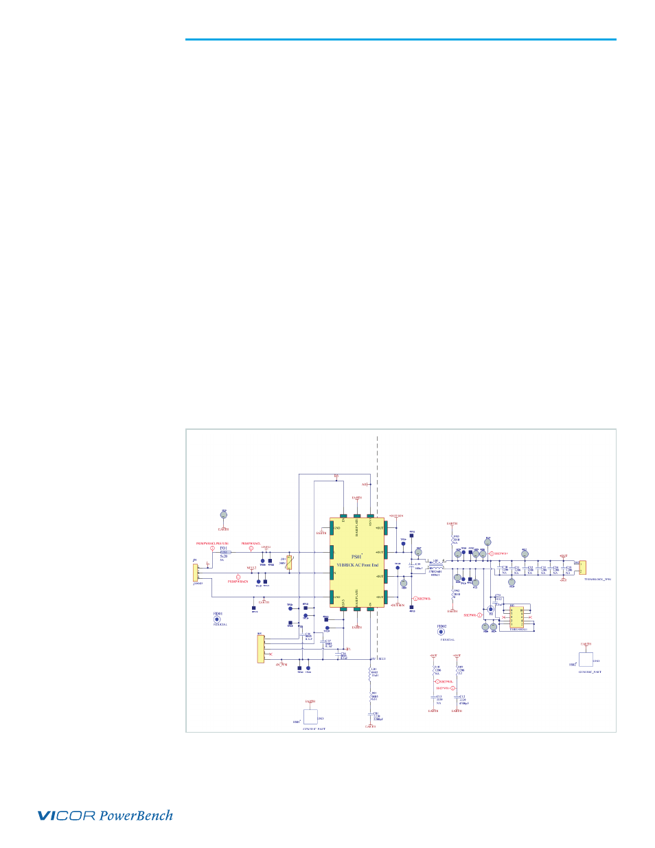
Figure 2
VI BRICK AC Front End
Output capacitor (C29) can be
added to reduce switching frequency
voltage ripple at the probe.
(Click on drawing to view larger.)