UVP LCD Screen User Manual
Page 3
LCD Screen
Page 2
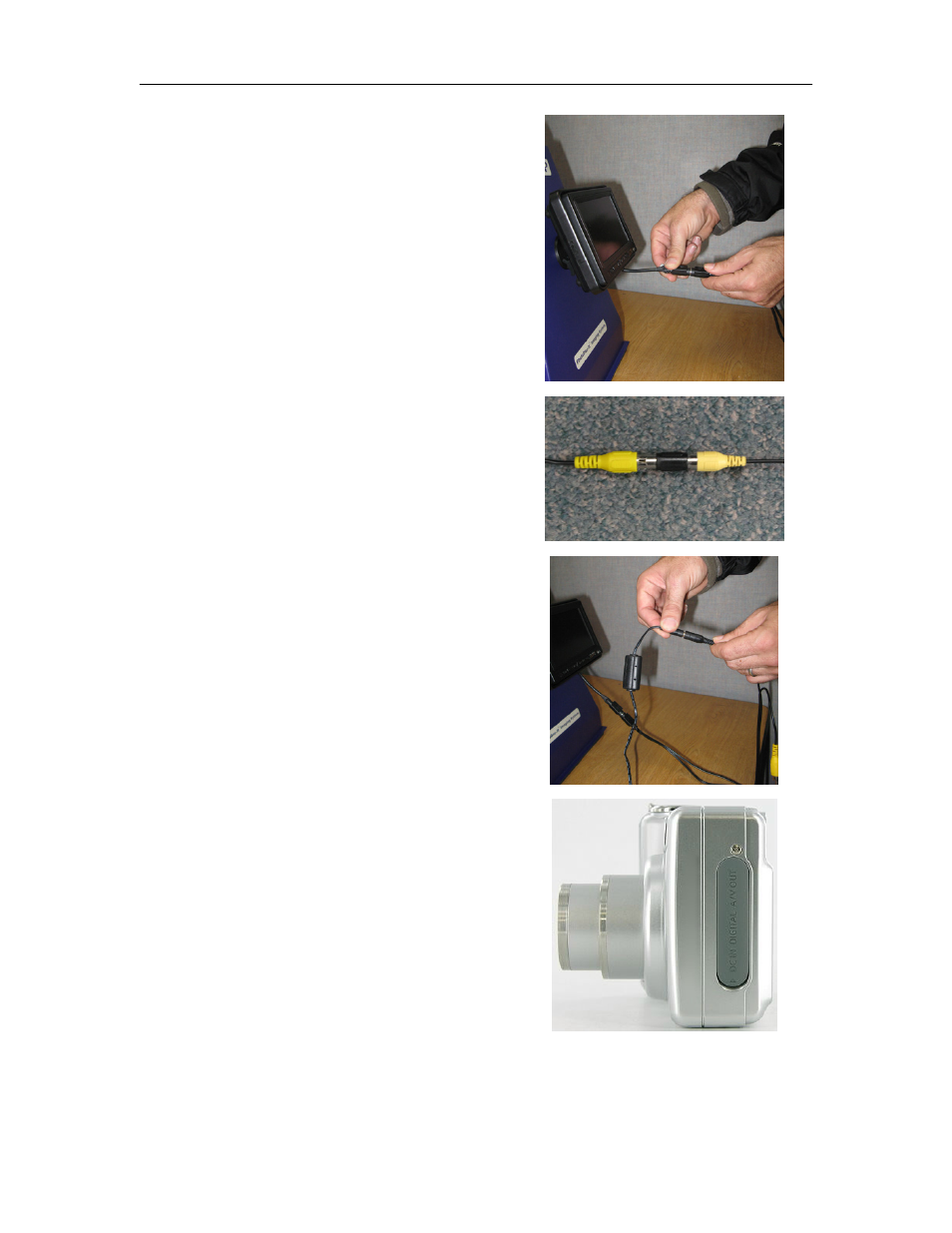
5. Connect the cables as shown in
the photograph. This is the audio
video (A/V) cable – five pin to the
screen cable.
6. Insert the black connector between
the two yellow connectors.
7. Connect the LCD screen cable to
the camera cable.
8. After installing the camera on the
hood per the PhotoDoc-It Imaging
System instructions, connect the
camera cable to the A/V out
camera port accessible on the side
of the camera.
This manual is related to the following products:
See also other documents in the category UVP Equipment:
- BioLite Xe (15 pages)
- Automated BioLite (14 pages)
- BioLite (13 pages)
- C-65 (8 pages)
- C-10 Series (2 pages)
- Crosslinkers (16 pages)
- DE-1 (1 page)
- DE-4 (2 pages)
- DE-50 (4 pages)
- HB-1000 Hybridizer (23 pages)
- HybriCycler (15 pages)
- HB-500 Minidizer (15 pages)
- Rocker Tray 76-0053-01 (1 page)
- iBox Anesthesia System (17 pages)
- BioChemi System with EpiChemi II Darkroom (38 pages)
- BioDoc-It System (18 pages)
- BioSpectrum Imaging System (22 pages)
- GelCam 310 Camera (8 pages)
- Chemi 410 (7 pages)
- OptiChemi 600 Camera (7 pages)
- MegaCam 800 Camera (5 pages)
- ChemiDoc-It Imaging System (14 pages)
- ChromaDoc-It Imaging System (10 pages)
- ColonyDoc-It Imaging Station (48 pages)
- DigiDoc-It Imaging System (11 pages)
- DigiDoc-It Drawer (1 page)
- EC3 Imaging System (10 pages)
- EpiChemi II Darkroom (10 pages)
- GelDoc-Ite Imager (12 pages)
- GelDoc-It 2 (21 pages)
- GelDoc-It TS2 (25 pages)
- GelDoc-It TS Imaging System (14 pages)
- GelMax Imager (12 pages)
- iBox Explorer Imaging Microscope (21 pages)
- iBox Scientia Small Animal Imaging System (16 pages)
- iBox Spectra Small Animal Imaging System (14 pages)
- MultiDoc-It Imaging System (10 pages)
- PhotoDoc-It Imaging System (10 pages)
- VisiDoc-It Imaging System (16 pages)
- Luminescence Calibration Standard (5 pages)
- SI-950 Ultraviolet Incubator (6 pages)
- Lab Table (2 pages)
- J-221 (2 pages)
- MS-100 Multi-Sense Optical Radiometer (1 page)