Performance curves selection procedure, Ma models with dc fan assemblies, Ma models – Thermal Transfer Systems MA Series User Manual
Page 4: No fan, core only), C e.t.d (°c) x correction factor
MA
www.thermaltransfer.com
262.554.8330
63
A
IR C
O
O
L
E
D
MA
Performance Curves
Selection Procedure
step 1
determine Heat load. Typical Rule of Thumb, - size cooler for
1/3 of the input horsepower. Heat load may be expressed as either
Horsepower or BTU/HR or KW/°C.
HP = BTU/HR ÷ 2545
BTU/HR = HP x 2545
step 2
determine entering temperature difference. (Actual E.T.D.)
(E.T.D.= Entering oil temperature – Entering Ambient air temperature)
The entering oil temperature is generally the maximum desired system
oil temperature.
Entering air temperature is the highest Ambient Air temperature the
application will see, plus – add any pre-heating of the air prior to its
entering the cooler. Pay special attention if air is drawn from the
engine compartment for cooling.
step 3
Find air Velocity Correction Factor
(Skip to Step 4 if using our DC Fan Assembly)
Calculate actual SFPM Air Velocity or SCFM (Standard Cubit Feet per
Minute) for selection using the Face Area from the table.
SFPM Air Velocity* = SCFM Air Flow
Square Feet Cooler Face Area
SMPM = SCMM
Square Meter Cooler Face Area
(SCFM Air Flow= SFPM Air Velocity x Square Feet Cooler
Face Area)
*If the Air Velocity calculated is different than the value in Step 4,
then recheck Corrected oil Pressure drop.
step 4
determine the Corrected Heat dissipation to use the Curves
englisH Version
Corrected (BTU/Hr) 100°F
Heat Rejection
=
Heat Load x Desired Air Velocity
†
E.T.D
x
Correction Factor
(BTU/HR) to use with selection chart
(Air Factor value not needed if using provided DC Fan assembly;
Omit in formula)
metriC Version
Corrected Heat
Heatload (kw)
Rejection KW =
Desired Air Velocity
°C
E.T.D (°C) x Correction Factor
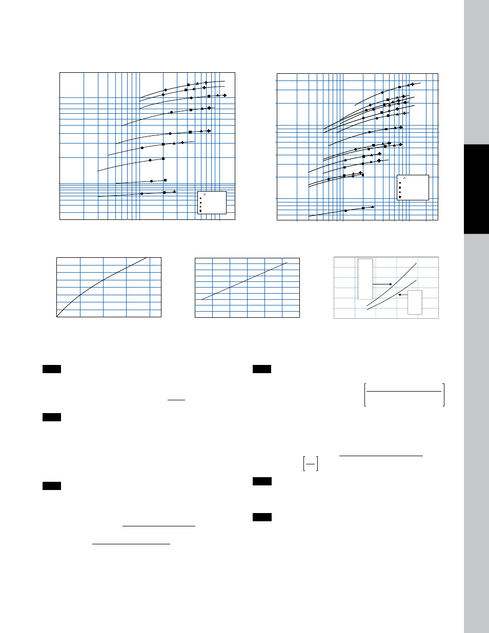
step 5
select model From Curves Enter the Performance Curves at the
bottom with the GPM oil flow and proceed upward to the adjusted
Heat Rejection from Step 4. Any Model or Curve on or above this point
will meet these conditions.
step 6
Calculate oil pressure drop Find the oil pressure drop
correction factor and multiply it by the Oil Pressure Drop found
on performance curve.
Listed Performance Curves are based on:
• 50 SSU (11 cSt) oil
• 1000 Standard Feet per Minute (SPFM) (304.8 MPM) Air Velocity
• 100° F (55.56° C) Entering Temperature Difference (E.T.D.)
If your application conditions are different, then continue with the
selection procedure.
BTU/HR = KW x 1895 x E.T.D.(°F)
°C
1
(3.79)
Heat Rejection BTU/HR @ 100F ETD
Oil Flow GPM (LPM)
MA-12-4A/B
MA-4-4A/B
MA-3-4A/B
MA-18-4A/B
MA-32-4A/B
100,000
200,000
10,000
1,000
20,000
40,000
60,000
80,000
Heat Rejection KW/C
0.5
1.1
0.05
0.005
0.1
0.2
0.3
0.4
2
(7.57)
20
(75.71)
40
(151.42)
60
(227.12)
80
(302.83)
100
(378.54)
4
(15.14)
6
(22.71)
8
(30.28)
10
(37.85)
MA-232-4A/B
MA-48-4A/B
MA-248-4A/B
= 5 PSI
= 10 PSI
= 15 PSI
= 20 PSI
(0.34 BAR)
(0.69 BAR)
(1.03 BAR)
(1.38 BAR)
Oil P
MA-3.5-4A/B
MA Models with DC Fan Assemblies
50 150 250 350
450
5.0
4.5
4.0
3.5
3.0
2.5
2.0
1.5
1.0
Viscosity (SSU)
Co
rr
ec
tio
n
Fa
ct
or
Pressure Drop
oil pressure drop Correction
0
500
1000
1500
2000
2500
3000
(152.4)
(304.8)
(457.2)
(609.6)
(762.0)
(914.4)
2.0
1.8
1.6
1.4
1.2
1.0
0.8
0.6
0.4
0.2
0.0
Face Velocity SFPM (smpm)
Co
rr
ec
tio
n
Fa
ct
or
Air Static
air static Correction
MA-4
MA-12
MA-18
MA-32
MA-48
MA-66
MA-82
MA-120
MA-232
MA-248
MA-3
MA-3.5
MA-8
MA-14
MA-20
0
500
1000
1500
2000
2500
(152.4)
(304.8)
(457.2)
(609.6)
(762.0)
3.00
2.50
2.00
1.50
1.00
0.50
0.00
Face Velocity FPM (mpm)
Air Static inH2O
76.2
63.5
50.8
38.1
25.4
12.7
0.00
Air Static mmH20
Air Static Pressure Drop
air static pressure drop
performance data Curve
10,000
5,000
20,000
40,000
60,000
80,000
100,000
200,000
300,000
400,000
500,000
0.05
0.03
0.1
0.2
0.3
0.4
0.5
1.1
1.6
2.1
2.6
MA-120
MA-82
MA-66
MA-48
MA-32
MA-20
MA-18
MA-14
MA-12
MA-8
MA-4
MA-232
MA-248
MA-3
= 5 PSI
= 10 PSI
= 15 PSI
= 20 PSI
(0.34 BAR)
(0.69 BAR)
(1.03 BAR)
(1.38 BAR)
Oil P
Heat Rejection BTU/HR @ 100F ETD
Heat Rejection KW/C
Oil Flow GPM (LPM)
1
(3.79)
2
(7.57)
20
(75.71)
40
(151.42)
60
(227.12)
80
(302.83)
100
(378.54)
4
(15.14)
6
(22.71)
8
(30.28)
10
(37.85)
200
(757.08)
400
(1514.16)
MA Models
(No Fan, Core Only)
performance data Curve